Facebook
 Google
 GitHub
 Linkedin
Electrolytic Capacitor Leakage Current
This article discusses Electrolytic Capacitors characteristic of leakage current and how it is important to allow 'self-healing'
Aluminum electrolytic capacitors ("alu-caps", "e-caps") are mission-critical components in many power electronic devices. The increasing demands for energy efficiency, the expanding use of renewable energy, and the growing share of electronics in the automotive industry have driven the widespread use of these components.
In many applications, service life and reliability of the device depend directly on the corresponding parameters of the electrolytic capacitors. While earlier contributions of the author gave an overview of electrolytic capacitor technology1 as well as the topics of lifetime estimation2, reliability3, and limits of voltage proof4, this article focuses on the leakage current of electrolytic capacitors.
Construction of Aluminum Electrolytic Capacitors
Aluminum electrolytic capacitors comprise a voltage range from a few volts up to approximately 700 V and offer a wide capacitance range from 1 µF up to about 1 F whilst having a compact construction at the same time. The surface of a highly roughened anode foil made from aluminum with a thin dielectric layer of aluminum oxide is fully contacted by a precise-fitting cathode, the electrolyte liquid (Figure 1).
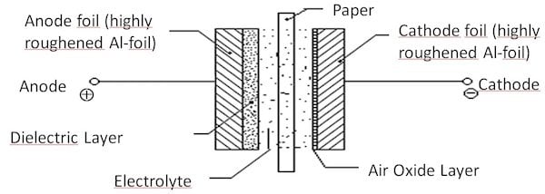
Figure 1. The internal structure of aluminum electrolytic capacitors.
An electrochemical process called "anodic oxidation" or "formation" produces the dielectric layer on the surface of the roughened anode foil. The quality of formation (i.e., the composition and thickness of the dielectric layer) is essential for the high reliability of electrolytic capacitors during operation. Figure 2 shows an electron micrograph of the surface of an etched high voltage anode foil.
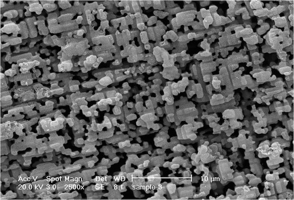
Figure 2. The surface of an etched anode foil.
Figure 3 shows the layer structure of the dielectric in cross section. On the aluminum foil ① is a layer of amorphous aluminum oxide ②, followed by crystalline ③, and finally a layer of hydrated oxide ④.
The compact molecules of the amorphous layer ② are only loosely bound, meaning they have little interaction with each other. This is useful when fluctuations of the electric field, induced by a ripple current, stimulate the molecules—less heat is dissipated compared to tightly coupled molecules. The "friction" between the molecules is low.
The molecules in the crystalline layer ③ are more closely arranged and offer good insulation resistance, which yields small leakage currents.
The large molecules of the hydrated layer ④ can be easily polarized and generate relatively high "friction losses". At higher temperatures, water molecules in the hydrated layer dissociate and weaken the crystalline layer ③, too, leading to an increase in leakage current.
Therefore, a goal for the development of new anode foils is reducing the thickness of the hydrated layer while simultaneously increasing the amorphous layer. Jianghai has its own factories for the formation of the anode material thanks to its strategy of vertical integration and can optimize the technology of the anode formation.
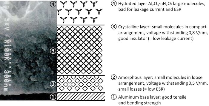
Figure 3. The layer structure of the aluminum oxide dielectric of a high-voltage capacitor. (Left: electron micrograph; Right: schematic representation)
Leakage Current
Defects in the dielectric of the anode are a major cause of the leakage current observed with electrolytic capacitors. Defects result from manufacture-related damages (cutting of the film, riveted connections of the tabs), crystal errors, the presence of foreign atoms in the aluminum base layer, mechanical stress (from winding), and partial dissolving of the oxide layer in the electrolyte.5
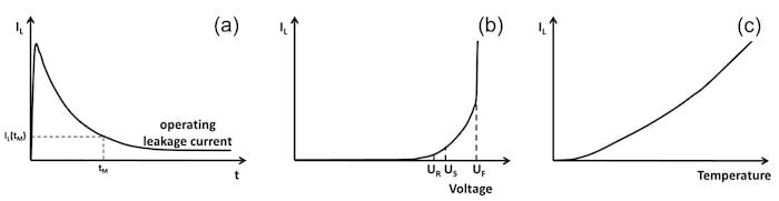
Figure 4. Electrolytic capacitor leakage current as a function of time (a), voltage (b), and temperature (c).
The dielectric absorption, bypass currents parallel to the capacitor cell, as well as tunnel effects6 make smaller contributions to the leakage current. Within a few minutes of connecting to voltage, the electrolytic capacitor leakage current decays almost exponentially and takes on an almost constant value, known as the operating leakage current (Figure 4 (a)).
The operating leakage current5 (as a measure of the forming condition of anode foil) depends on the time, applied voltage, temperature, and history of the capacitor (Figure 4 (a-c)). Typical values of the operational leakage current range between 5-15% of the data sheet value of leakage current amount and are usually reached after several minutes of continuous operation.
Storage of Electrolytic Capacitors
The leakage current specified in the data sheet shall be valid even after a long, voltage-free storage period, giving it a much higher numerical value than the operating leakage current. The oxide layer dissolves to a certain extent as a function of temperature and electrolyte composition, because without any voltage applied, the oxide layer cannot regenerate ("self-healing").5
Thus, devices kept for maintenance purposes should be operated from time to time. The periods of time for these brief regeneration operations depends on the type of electrolytic capacitors used but typically fall in the range of every several years.
When storing fresh, not yet assembled or soldered capacitors, Jianghai recommends not exceeding a period of 12 months after arrival to the end user prior to process and use. Longer storage times may negatively affect the solderability or cause increased leakage current during the first operation. Depending on the series and the environmental conditions during storage, longer storage periods may be agreed upon individually.
While low-voltage capacitors (up to 100 V rated voltage) with solvent-based electrolyte systems are usually very stable, high-voltage capacitors (from 160 V rated voltage) with ethylene glycol-based electrolytes, in particular so-called "low ESR" types with aqueous electrolytes, may exhibit an increase of leakage currents throughout their lifetime.
About 15-30 minutes of operation of the electrolytic capacitors via a resistor (low-voltage: 100 Ω, high-voltage: 1 kΩ, see DIN EN 60384-4:2017-04, section 4.1 "pretreatment"7) at a voltage increased gradually to rated voltage may heal the weak spots in the dielectric, lowering the leakage current below the datasheet value.
Balancing of Capacitor Banks
In a series connection of capacitors, the voltage across the capacitors splits according to the ratio of insulation resistances of the capacitors (or in relation to the reciprocal leakage currents of the capacitors).8
To ensure a uniform distribution of the voltage, the quiescent current IQ through the voltage divider resistors in Figure 5 should exceed the (operating) leakage current by several times. The use of electrolytic capacitors from the same production lot is beneficial because they generally have fewer deviations of leakage currents among them than products from different batches.
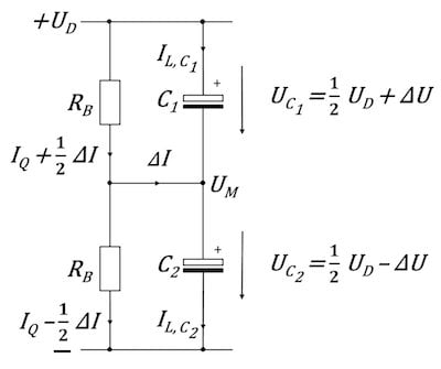
Figure 5. Passive balancing of e-cap voltages with resistors.9
The midpoint voltage Um can be computed as:8
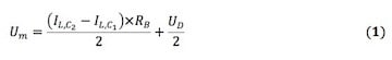
Equation 1 shows that the midpoint voltage Um differs from the desired ideal value of UD/ 2 by a value which is proportional to resistance RB and leakage current difference.
For the estimation of the balancing resistors RB, a good compromise between power losses and acceptable voltage difference needs to be found.
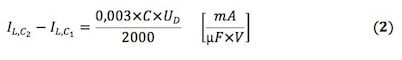
The leakage current difference of the electrolytic capacitors at upper category temperature can be estimated by Equation 2:8
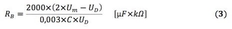
Solving Equation 1 for RB and substituting the expression for IL,C2 - IL,C1 by Equation 2 yields:
For ideal balancing resistors, i.e., with identical resistance values, the midpoint voltage would equal the electrolytic capacitor’s rated voltage. Real resistors, however, are subject to a tolerance, so the midpoint voltage will also deviate from the ideal of the half DC link voltage. With a tolerance of the resistance values of e.g. ±5%, the resulting midpoint voltage will deviate from the ideal value by almost 10% in the worst case.8 It is therefore advisable to use low tolerance resistors and to choose a midpoint voltage below the rated voltage of the capacitors when employing passive balancing.
The Many Options of Intermediate Circuit Topologies
For a parallel connection of several branches of electrolytic capacitors connected in series, another question arises for the topology of the balancing circuit: are all branches individually balanced (Figure 6a) or do the midpoints of all branches need to connect with central balancing applied (Figure 6b)? Or, if neither of those options works, does the balancing of capacitors need to be performed in groups (Figure 6c)?
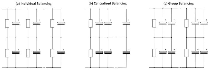
Figure 6. Topologies of passive balancing for e-cap DC-link circuits.
Each of these topologies (a, b, and c) have specific advantages and disadvantages:8
(a) Individual Balancing
Advantage: In case of the failure of an individual electrolytic capacitor due to short circuit, just one other capacitor in the branch of the defective electrolytic capacitor suffers from overvoltage. The remaining electrolytic capacitors in the bank are initially unaffected by the failure of a single branch of the bank.
Disadvantage: There is a higher wiring effort with more resistors and connections (and thus higher space and cost requirements).
(b) Centralized Balancing
Advantages: In the steady-state, average capacitance and leakage current values of the upper and lower half of the bank will approach each other. There are only two central balancing resistors used, which may have relatively high ohmic values as the upper and lower half of the DC-link are similar.
Disadvantage: In case of failure of a single electrolytic capacitor due to short circuit, several electrolytic capacitors may be damaged by overvoltage. Care must be taken to achieve a uniform distribution of the current flow into the individual branches of the capacitor bank as well as a homogenous ambient temperature distribution in the vicinity of the capacitor bank.
(c) Group Balancing
Figure 6c shows a possible combination of individual (a) and centralized balancing (b). This topology combines the advantages and disadvantages of the individual variants.
In addition to passive balancing, the so-called active balancing is also found in large inverters. The active balancing circuit concept, which can, for example, be realized in cascode-voltage follower topology, offers some advantages:9
- It can be used resistors with small losses
- Energy cost savings over the lifetime of the inverter
- Better balancing accuracy in the steady-state
- Low-cost solution
However, a disadvantage of active balancing is that no automatic discharge of the DC-link intermediate circuit occurs when the inverter is switched off. The safe discharge of the intermediate circuit when switched off must, therefore, be ensured by other means.
Summary
Due to their design, aluminum electrolytic capacitors have the peculiarity of requiring an operating leakage current to allow for the so-called "self-healing". The leakage current is closely related to the composition and the construction of the dielectric layer. A closer examination of the dielectric layer shows that it consists of various layers of aluminum oxide. By a suitable process control during the forming of the anode material, the properties of the dielectric can be optimized. In electrolytic capacitors for demanding applications, providers such as Jianghai, which rely on their own formation facilities for the anode foils, are offering technical advantages.
The leakage depends on the duration of the operation, the operating voltage, temperature as well as the prehistory of the electrolytic capacitors. The duration of a voltage-free storage of electrolytic capacitors is time-limited. The difference in leakage current between electrolytic capacitors (even if they come from the same production lot) is so large that it requires a balancing of the voltage drop over a series of capacitors. This article presented the method of passive balancing and gives practical advice on properly dimensioning the resistance values, and gave a method for active balancing.
The applicability of the models and their results shown here depend on individual cases, the series, and the application. Therefore, close project monitoring and confirmation of assessments by the electrolytic capacitor manufacturer is always required.
About the Author
Dr. Arne Albertsen studied physics focusing on applied physics at the University of Kiel. He earned diploma (1992) and PhD (1994) degrees on the measurement and analysis of current-time-series of ion channels in biological membranes. In industry, he worked in various areas of environmental and process engineering plant construction. Since 2001, he is dedicated to the marketing and sales of passive and discrete active components for leading companies like Vishay and KOA. Since November 2008, he is responsible as Senior Sales Manager for several European key account customers of Jianghai Europe Electronic Components GmbH (Krefeld). The focus of Dr Albertsen is the design-in and application support for capacitors in professional industrial applications. Since 2011, Dr Albertsen volunteers as an expert for electrolytic capacitors and Deputy Chairman in the standardization body „K611“ of the DKE in DIN and VDE.
References
- Albertsen, A., Elko-Grundlagen: Das „1 × 1“ für Entwickler, Elektronik Components Oktober 2016, 35-39 (2016)
- Albertsen, A., Lebe lang und in Frieden! Hilfsmittel für eine praxisnahe Elko-Lebensdauerabschätzung, Elektronik Components 2009, 22-28 (2009)
- Albertsen, A., Auf eine sichere Bank setzen – Zuverlässigkeit von Elektrolytkondensatoren, Elektronik Components 2010, 14-17 (2010)
- Albertsen, A., Gebührenden Abstand einhalten! – Spannungsfestigkeitsbetrachtungen bei Elektrolytkondensatoren, Elektronik Power, 54-57 (2011)
- Thiesbürger, K.H., Der Elektrolytkondensator, Roederstein, Landshut (1991)
- Both, J., Stromsparer – Reststromverhalten moderner Elektrolytkondensatoren, BCcomponents, Hamburg (2001)
- DIN EN 60384-4:2017-04, Festkondensatoren zur Verwendung in Geräten der Elektronik – Teill 4: Rahmenspezifikation – Aluminium-Elektrolyt-Kondensatoren mit festen (MnO2) und flüssigen Elektrolyten, DIN Deutsches Institut für Normung e. V., Berlin (2017)
- CLC/TR 50454:2008, Guide for the application of aluminium electrolytic capacitors, CENELEC, Brüssel (2008)
- Ertl, H., Wiesinger, T., Kolar, J.W., Active voltage balancing of DC-link electrolytic
- Capacitors, IET Power Electronics, 2008, Vol. 1, No. 4, pp. 488–496 (2008)
This article originally appeared in the Bodo’s Power Systems magazine.