Facebook
 Google
 GitHub
 Linkedin
Qorvo Says its New 1200 V SiC FETs Sport Industry’s Best Figures of Merit
The six FETs, members of the fresh UF4C/SC series, feature industry-leading marks for on-resistance, claims Qorvo (formerly UnitedSic), and target the 800 V power buses now common in EVs.
With PCIM Europe 2022 in full swing this week in Nuremberg, Germany, Qorvo introduced six new 1200 V FETs to its Gen 4 line of silicon carbide (SiC) offerings, the first additions since last September. With its new devices, the company is touting superior RDS(ON)s, with one FET each listed at 23 and 30 mΩ, and two more at both 53 and 72 mΩ, all of which sport top figures of merit.

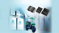
Qorvo's new 1200 V FETs, in TO-247 three-lead and four-lead packages. Images [modified] used courtesy of Qorvo
As the EV industry transitions from standard 400 V powertrains to more demanding 800 V models, those characteristics are crucial, said Anup Bhalla, Chief Engineer of Qorvo’s Power Devices unit.
“In electric vehicles, this move to higher voltages is inevitable and these new devices, with four different RDS(on) classes, help designers select the best possible SiC choice for every design,” Bhalla said.
Figures of Merit — The Numbers
In its release announcing the new series, Qorvo offered its FETs’ following specifications for four of the most popular figures of merit (FOM):

On-resistance figures of merit for Qorvo's new 1200 V SiC FETs. Screenshot used courtesy of Qorvo
All six of the UF4C/SC devices are offered in the industry-standard four-lead kelvin source TO-247 package, which allows for cleaner switching and higher performance levels. The 53 and 70–milliohm devices are also available in the TO-247 three-lead package.
Thanks to advanced silver-sinter die attach and wafer-thinning processes, series members should boast superb reliability, based on their well-managed thermal performance.
Series Commonalities
The devices are all of a “cascode configuration,” which involves packaging a normally-on SiC JFET with a silicon (Si) MOSFET to produce a normally-off SiC FET device, per Qorvo.
The device’s standard gate-drive characteristics (4.8 V, typical) allows for a true “drop-in replacement,” the company says, to Si IGBTs, Si FETs, SiC MOSFETs or Si superjunction devices.
Throughout the series, devices whose designations end in “3KS” are offered in the three-leaded TO-247 packages, while those with “4KS” endings come in TO-247-4L Kelvin packages.
Series members feature gate charges (QG) of 37.8 nC.
The UF4C120053K3S and UF4C120053K4S
The UF4C120053K3S and UF4C120053K4S both sport 53 mΩ RDS(ON)s, with a body diode VFSD of 1.28 V.
The latter’s four-lead Kelvin package features a reverse recovery charge (Qrr) of 216 nC, while the rating for its non-Kelvin partner is 117 nC.
The UF4C120070K3S and UF4C120070K4S
These SiC FETs feature RDS(ON)s of 72 mΩ, with a body diode VFSD of 1.43 V. Qrr for the Kelvin and non-Kelvin devices is 119 and 72 nC, respectively.
The UF4SC120030K4S and UF4SC120023K4S
The UF4SC120030K4S and the UF4SC120023K4S feature RDS(ON)s of 30 and 23 mΩ, respectively, and are available only in four-lead Kelvin packages.
For the UF4SC120023K4S, Qrr is 341 nC and VFSD is 1.2 V. The corresponding figures for the UF4SC120030K4S are 277 nC and 1.22 V.
Applications
- Onboard charging (OBC)
- Traction inverters
- On-board EV DC/DC converters
- Industrial power supplies
- DC/DC solar inverters
- Welding machines
- Uninterruptible power supplies (UPS)
- Induction heating
Environmental Compliance
These new FETs are RoHS-compliant, Pb-free, and halogen-free.
Regulatory notes
ESD protection ratings for these semiconductors are HBM class 2 and CDM class C3.
Physical Considerations
Qorvo's 1200 V SiC FETs operate over a junction temperature range of -55 to 175 ℃.
Getting to Market Faster
Covering the company’s entire lineup of 1200 V SiC FETs, Qorvo’s FET-Jet Calculator is a free online design tool that makes it easier to evaluate the efficiency, component loss, and junction temperature rise of devices used in a wide variety of topologies, including AC/DC and isolated/non-isolated DC/DC converters. To enable optimum solutions, designers can specify conditions under which to compare both single and paralleled devices.