Facebook
 Google
 GitHub
 Linkedin
Pulse Current Sources for High Current Wafer Tests up to 3000A
Ed-k has developed new pulse current sources for dynamic wafer testing of IGBTs.
As far back as 2002, ed-k developed the world’s first commercially available inductance meter that works according to the pulse measurement principle. That was followed a short while later by the first model of the well-known Power Choke Tester DPG10/20 series, which is a fully integrated, extremely compact, and simple-to-use measuring system with an enormously wide range of applications for all inductive power components. The device uses powerful PC software with a very simple-to-use graphic user interface. The DPG10/20 series has been continuously developed and successively supplemented by what is now a total of 9 further models for smaller currents down to the mA range and larger currents up to 10 kA.
Ed-k’s Power Choke Tester DPG10/20 series has long since established itself worldwide as the quasi-standard for developing, producing, and quality control of inductive power components.
Now, based on the pulse current sources used in the DPG10 series, ed-k has developed new pulse current sources up to 3 kA for the dynamic wafer testing of IGBTs, as previously available test systems could not cover this current range.
Two fundamental innovations in the Power Choke Tester DPG10/20 series will be presented in the second part of this article: an additional application, which has been optimized for routine testing in mass production, and new test adapters that enable the measurement of very small inductance values as low as 50 nH.
Measuring Principle of the Power Choke Tester
In the pulse measurement principle of the DPG10/20 series, a square-wave voltage pulse is applied to the test specimen. The amplitude is adjustable and is conveniently selected so that it corresponds approximately to the voltage at the inductor in the real application. A current curve is then established in the inductor, whose slew rate di/dt is dependent on the current-dependent inductance L(i). When the preset maximum current or preset pulse width is reached, the measuring pulse is switched off again.

Figure 1. Measurement pulse of the Power Choke Tester DPG10 CH3: 20A/div, CH4: 50V/div. Image used courtesy of Bodo’s Power Systems [PDF]
From the curve of the current i(t) and the voltage v(t) on the test specimen, the following variables can be calculated with a single measuring pulse:
- Differential inductance Ldiff(i) and Ldiff(∫Udt)
- Amplitude inductance Lamp(i) and Lamp(∫Udt)
- Flux linkage ψ(i) • Magnetic co-energy Wco(i)
- Flux density B(i), if the core cross-section and number of turns are known
- Also suitable for 3-phase chokes with the optional 3-phase Extension Unit
Remark: The amplitude inductance Lamp(i) is often also referred to as the secant inductance Lsec(i).

Figure 2. Measurement diagram Ldiff(i). Image used courtesy of Bodo’s Power Systems [PDF]
The behavior of all core materials is strongly dependent on frequency and amplitude. Since the measuring pulse has the same rectangular curve shape as in most power electronics applications and the same amplitude and frequency or pulse width as in the real application, the most realistic measurement results are obtained. Other measurement methods, such as the small-signal measurement of LCR meters and the pulse measurement method with SCR, use measurement signals that have nothing to do with the real conditions. Therefore, the results are usually not very meaningful.
The pulse voltage source takes the pulse energy from a capacitor bank. If its energy content is significantly higher than the energy withdrawn during the pulse, the voltage of the measuring pulse is roughly constant. Due to the principle, there is no upper limit for the capacitance of the capacitor bank, regardless of the type of test specimen. That is one of the reasons for the extremely wide application range of the Power Choke Tester DPG10/20 series for virtually all inductive power components, from small PCB-mounted inductors to reactors in the MVA range weighing several tonnes.
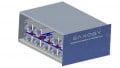
New Device Series of PCS10 Pulse Voltage Sources
One of the core components of the pulse inductance meters from ed-k is a powerful pulse voltage source, which has to be able to supply currents of up to 18 kA, depending on the model. The dynamic wafer testing of IGBTs also requires powerful pulse voltage sources for ramp-shaped currents up to several kA. Previously available test systems for dynamic wafer testing cannot cover this current range.
For this reason, the world’s leading German manufacturer of power semiconductors has developed its own test system. It turned to ed-k for the necessary high-power pulse voltage source. Initially, the idea was to “misuse” a Power Choke Tester DPG10- 3000B/E as a pulse voltage source. However, this simple solution was unsatisfactory for the requirements in series production with test cycle times of < 400 ms.
Therefore, in cooperation with this semiconductor manufacturer, ed-k developed such a pulse voltage source for currents up to 3 kA based on the Power Choke Tester DPG10 series. It meets the specific requirements of dynamic wafer testing, such as short cycle times and fiber optic trigger outputs to activate the drivers for the IGBT chips. This ultimately resulted in the new PCS10 device series.
Table 1. Technical data of the PCS10 series
| Model | PCS10-1000B | PCS10-3000B | |
| Max. pulse current | 1000A | 3000A | |
| Pulse voltage | 10 – 400V | ||
| Pulse width | 1µs – 260ms | ||
| Max. pulse energy | 1250J | 2500J | |
| Pulse repetition rate | up to 5Hz | ||
| Average pulse power | 150W | ||
| Load | resistive or inductive | ||
| Control interface | USB and RS232 | ||
| Trigger outputs | Fiber optic and TTL |
Dynamic Wafer Test
In dynamic wafer testing, the RBSOA (reverse bias safe operating area) and the SCSOA1/SCSOA2 (short circuit safe operating area) are measured according to the IEC60747-9 standard. The dynamic wafer test can detect defects in the chip that would not be detectable with a static test and can lead to failure during operation (e.g. latch-up).
To check the RBSOA, the clamped inductive load test is executed. Here, the IGBT chip is switched on with an inductive load of a few μH. The voltage of the pulse source does not need to be very high and is usually in the range of 50-200 V. A linearly increasing current then results in the load and in the IGBT. The IGBT is switched off once the desired current level is reached. The inductive load then drives the current further, so that the voltage at the IGBT rises sharply. The collector voltage is limited by a clamping circuit to a value below the breakdown voltage to prevent immediate destruction of the IGBT due to overvoltage. The IGBT chip must therefore be able to withstand both the full current and the clamping voltage for a short time during the shutdown process without being damaged.

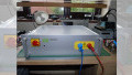
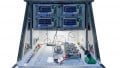
Figure 3. Test system for the dynamic wafer test. Image used courtesy of Bodo’s Power Systems [PDF]
If the chip has a defect in its crystal structure, this usually leads to an explosion during the clamped inductive load test. The extent of the destruction on the wafer and the contact needles depends on the energy or current. Therefore, a sensible strategy is to first perform the test with a small current to minimize the destruction in the event of a failure and only then to repeat it with the full specified current.

Figure 4. Simplified diagram of the RBSOA test according to IEC60747-9. Image used courtesy of Bodo’s Power Systems [PDF]
In the SCSOA1 test, the switch-on is tested for a short circuit. This test is performed with a higher voltage, e.g. 50% of the maximum collector-to-emitter voltage Vcemax. The current in the IGBT chip then increases very quickly until it is limited by the desaturation of the chip. In large IGBT chips, this can be up to 3 kA. At the same time, the collector voltage remains at the full value of the voltage source. The power loss is extremely high and is in the MW range. Depending on the specification, the IGBT chip must be able to withstand this for a few µs without being damaged. Subsequently, the IGBT has switched off again.

Figure 5. Destruction of the chip after the clamped inductive load test due to a defect in the crystal structure. Image used courtesy of Bodo’s Power Systems [PDF]

Figure 6. Simplified diagram of the SCSOA1 test according to IEC60747-9. Image used courtesy of Bodo’s Power Systems [PDF]
The SCSOA2 test is similar. Here, however, the load is short-circuited with the IGBT switched on.
Further DPG10/20 Series Developments
Until now, the Power Choke Tester DPG10/20 series has been delivered with very powerful software that offers extensive measurement options.
This software is ideally suited for laboratory operation and for the routine testing of small series with manufacturing batches of up to several hundred items. This software was less suitable for the routine testing of very large quantities, as the measured data were saved in files in XML format. With very large numbers of items, these files become too big and can only be handled with difficulty.
However, it has also been possible up to now to use the DPG10/20 series in mass production. With the help of a supplied DLL, the devices can be controlled relatively easily by proprietary applications and integrated into customer-specific automated test environments (ATE). For control with proprietary applications, there is extensive technical support such as example programs for .NET, CS, and C+.
Control by means of LabVIEW is also possible. VIs and corresponding technical support are also provided for this purpose.
Many major customers have already chosen the option of integrating the devices into their own test environments with the help of the DLL provided. For example, a well-known international manufacturer from the solar industry already uses more than 75 devices of the type DPG10-1000B for 100% routine testing of large quantities.
For the integration in the customer’s own ATE, however, a certain amount of programming effort and the corresponding skills are required on the part of the customer. For this reason, ed-k has extended the software package for the Power Choke Tester DPG10 series with a plug-and-play solution for mass production. In addition to the already familiar application for laboratory and small series use, there is now a second application that has been specially designed for mass production.
The most important innovations in the production application are the storage of measured data in a database instead of in files as well as a completely new user interface that has been optimized for use in mass production in a harsh production environment.
The large amounts of data generated during mass production can only be stored sensibly in a database. Since many companies already use databases in production, the productive application can deal with different databases. This allows companies with several production sites to access the same database at all locations.

Figure 7. Graphical user interface of the new DPG10 application for mass production. Image used courtesy of Bodo’s Power Systems [PDF]
The user interface of the productive application is limited exclusively to the operating and display elements necessary for routine testing, so that operation by unskilled personnel is also not a problem. Of course, an automatic PASS/FAIL test is carried out according to the specification of corresponding limit value curves. The display elements of the user interface are configurable. For example, a large colored display area for PASS (green) or FAIL (red) is already clearly visible on the monitor from several meters away, so that the defective part can be sorted out. Alternatively, however, the measured inductance curve can also be displayed.
For high efficiency or short test times, the use of a barcode scanner is recommended. This means that, in addition to contacting the device under test, the test personnel only need to scan the barcode. Everything else runs automatically. With automatic handling and contacting of the DUT via a specimen-specific adapter, a fully automatic test is even possible.
After the redesign of the Power Choke Tester DPG10 series last year, which enables significantly shorter measuring times, cycle times as short as 2 seconds can be achieved in fully automatic testing.
However, the familiar application for laboratory and small series testing has also been significantly further developed. The application is now available in 32-bit and 64-bit versions. It can store the measured data both in a well-known manner as xml files and in a database. Export from the database and conversion into xml format is also possible so that compatibility with older devices and measured data is guaranteed.
Measurement of Low-inductance Components Down to 50 nH
The measurement of low-inductance components < 1 µH is basically problematic, regardless of the measuring device and measurement principle used. In the pulse measurement principle of the Power Choke Tester DPG10 series, it is above all the parasitic inductances, the inductive coupling between the force leads and the sense leads, as well as the maximum sampling rate that are decisive.
Together with the inductance of the test specimen, the parasitic inductance of the test leads as well as the device’s internal parasitic inductance form an inductive voltage divider. If these parasitic inductances are larger or even much larger than the inductance of the test specimen, then only a small part of the voltage of the measuring pulse is dropped across the test specimen. Most of it is dropped across the parasitic inductances. This worsens the measuring accuracy, even if a 4-wire measurement is always used. In the 4-wire measurement, the voltage is tapped directly on the test specimen via separate sense leads.
To prevent the display of incorrect or inaccurate measurement results, measurements must be discarded if too much of the pulse voltage drop across the parasitic inductances. In order to be able to measure the smallest possible inductance values, the parasitic inductances must therefore be minimized.
The test leads play a significant role in parasitic inductances. The optimized test leads made of highly flexible litz wire with a 6 mm² copper cross-section and a length of 0.6 m from the standard scope of delivery of the DPG10 series already have an inductance of more than 700 nH. In conjunction with further parasitic inductances for the alligator clips on the test specimen and the device’s internal inductances, this limits the measurement to values of 500 nH at the most.
In order to extend the area of use of the DPG10 series down to 50 nH, ed-k has developed a set of 3 different test adapters that can be plugged directly into the sockets on the front panel of the devices without the use of test leads. The influence of the test leads can thus be completely eliminated. These test adapters are optimized for minimum parasitic inductances. In conjunction with the optimum internal design of the DPG10 series and the associated extremely low parasitic inductances, measurement can be performed in some cases down to less than 50 nH!

Figure 8. Test adapter MAB1/2/3 for the Power Choke Tester DPG10 series. Image used courtesy of Bodo’s Power Systems [PDF]
The test adapters are particularly suitable for SMD components and through-hole PCB-mounted components. A separate test adapter is required for each current range.
The measurement of low inductance values is also limited by the minimum possible pulse width, which is mainly limited by the maximum sampling rate, because the lower the inductance, the greater the slew rate of the current, and thus the faster the preset current limit is reached. The A/D converters of the DPG10 series, an ed-k proprietary development, enable both very short measuring pulses due to a high maximum sampling rate and very long pulses due to an arbitrarily reducible sampling rate. Thus, an extremely wide pulse range from 3 μs up to 70 ms can be covered.
The maximum pulse width is not determined by technical limits but has been limited to 70 ms due to safety considerations for the user. However, this is sufficient even for chokes that are used in a frequency range of <5 Hz.
In the course of the continuous further development of the DPG10 series, two new models were developed with a maximum measurement current of up to 2000 A. The DPG10-2000B and DPG10- 2000B/E models replace the DPG10-1500B and DPG10-1500B/E models, which will still be available for the time being. The current measurement ranges are 20 A, 200 A, and 2000 A, with the usual gradation 1:10, as with the other models. This results in better accuracy in the widest measuring range compared to the 1500 A models. The other technical data are the same as those for the 1500 A models.
This article originally appeared in Bodo’s Power Systems [PDF] magazine.