Facebook
 Google
 GitHub
 Linkedin
Programmable Surge Current Tester for Power Semiconductors
The often cited I2t value describes a power semiconductor’s ability to withstand surge current events. However, the dependency on the current shape is usually overlooked. This article gives a short introduction to a surge current tester with arbitrary output current waveform and exceptionally low output current ripple, which enables a wide range of surge current tests.
This article is published by EEPower as part of an exclusive digital content partnership with Bodo’s Power Systems.
The often cited I2t value describes a power semiconductor’s ability to withstand surge current events. However, the dependency on the current shape is usually overlooked. This article gives a short introduction to a surge current tester with arbitrary output current waveform and exceptionally low output current ripple, which enables a wide range of surge current tests.
Surge current withstand capability is an important ability for power semiconductors, e.g., in case of a fault event. The overcurrent capability of power semiconductors is quantified by the maximum surge current ITSM and the I2t-value. Both parameters are defined for a half-sinusoidal current pulse with a pulse duration TP = 10 ms. This definition does not, however, take different current waveforms or multi-pulse surges into account.
To perform experiments for a wide range of applications, a wide range of amplitudes, pulse durations, and waveforms is required. Well-known standard solutions using passive components (e.g., resonant or capacitor discharge circuits) do not meet these requirements, as they can only realize fixed current waveforms with frequencies and time constants depending on the passive components used.
Alternatives utilizing active switches do exist but come with their own drawbacks. An example is a massive parallelization of MOSFETs used as analog amplifiers enables a programmable current waveform but causes very high losses, which limits pulse duration and repetition rate.
Surge Current Source Design
Requirements for the surge current source presented in this article include a freely programmable current waveform with a maximum amplitude beyond typical thyristor maximum peak currents, which can exceed 90 kA. To realize pulse trains corresponding to multiple grid-frequency periods, pulse widths of several tens of ms are required. Further requirements include high accuracy and a low device under test (DUT) current ripple.
Table 1 lists the key parameters of the surge current source. To meet the requirements, a modular approach has been chosen: the current source is comprised of 16 cells, each consisting of two IGBT half-bridges, a dc-link capacitor CDC = 9 mF, and one output inductor Lout = 50 μH per half-bridge.
Table 1. Key parameters of the surge current source
| Parameter | Range | Notes |
| maximum DC-link voltage | 1200 V | low voltage, (<1500 V DC) |
| max. IGBT voltage | 1700 V | low voltage IGBTs |
| max. stored energy ΣWC | 104 kJ | - |
| max. current Ipk | 100 kA | - |
| max. current ripple | 60 A | equals 0.06 % (at 100 kA) |
| min. current rise time t_r | 380 µs | controller-limit |
| maximum diDUT⁄dt | 768 A/µs | hardware-limit |
| 263 A/µs | resulting from tr (at 100 kA) | |
| pulse width Tp |
≈ 1 ms … ≈ 100 ms |
min/max width, dependent on the waveform, peak current, and DUT |
The structure of a cell is depicted in Figure 1, together with its possible output configurations: The cells can be used as two independent half-bridges in high current mode (HCM) or as one full-bridge in dynamic current mode (DCM).
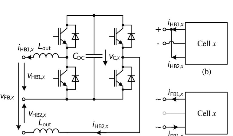
Figure 1. Electrical structure of one of the cells in the surge current tester (a). The cells can be configured in HCM (b) or DCM (c). Image used courtesy of Bodo’s Power Systems [PDF]
In Figure 2, a photograph of the setup can be seen. Mechanically, the current source is divided into two halves, with 8 cells each. To limit the magnetic forces, the full current only flows through the DUT itself. The copper bars connecting eight cells per side to the DUT only carry half the current, reducing the occurring magnetic forces by a factor of four. The copper bars on each side are clamped together with insulating clamps to withstand the remaining magnetic forces.
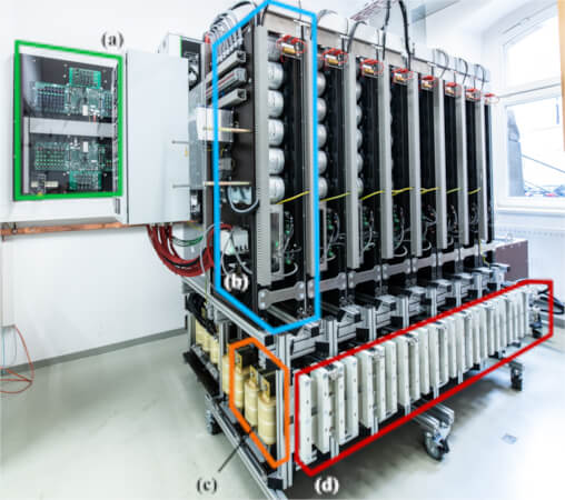
Figure 2. Photograph of the high current source. Highlighted parts are (a) the control platform, (b) one of 16 cells, (c) inductors Lout, and (d) high current bus bars. Image used courtesy of Bodo’s Power Systems [PDF]
The control platform, see Figure 2(a), is responsible for communication with the operator’s computer and runs the control algorithms. It handles a multitude of signals. This includes measurements: 32x current and 16x dc-link voltage, control signals: 32x enable, 32x PWM, 32x GDU feedback as well as auxiliary signals: 2x arc detection, 4x discharge relays, 16x delta-sigma clock. The half-bridges are switched interleaved with an effective switching and control cycle frequency of 96 kHz. All signals are transmitted using fiber optics.
Experimental Test Results
The performance of the surge current tester has been evaluated by many practical experiments, both in HCM and DCM. Two examples are shown here. In Figure 3, a comparison of halfsine current pulses with different amplitudes can be seen and realized in HCM. Since the cells are configured as half-bridges in HCM, the falling current slope is only determined by the losses in the system. In DCM, on the other hand, the cells are configured as full-bridges, which enables negative output voltages and thus a controlled negative diDUT/dt.
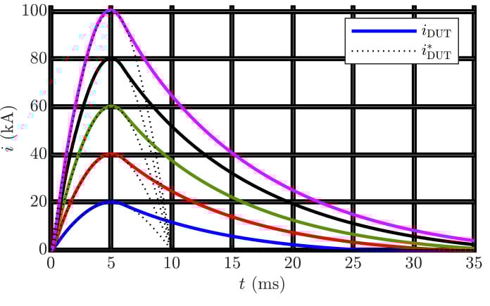
Figure 3. Comparison of current iDUT measured by the control platform and target current trajectory i*DUT. Short circuit load. HCM. Image used courtesy of Bodo’s Power Systems [PDF]
Figure 4 shows a waveform resembling the outline of the Frauenkirche in Dresden.
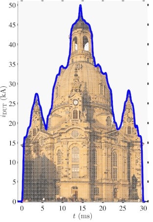
Figure 4. Example of a dynamic current waveform: DUT-current tracing a profile of the Frauenkirche in Dresden. Source of photograph: Thyristor as load. DCM. Image used courtesy of Bodo’s Power Systems [PDF]
Modular Surge Current Tester
This article is a short introduction to the authors’ recently built programmable, modular surge current tester. The basic principles and abilities of the current source are described and shown with experimental test results.
This article originally appeared in Bodo’s Power Systems [PDF] magazine and is co-authored by Stefan Wettengel, Andreas Hoffmann, Jonas Kienast, Lars Lindenmüller, and Steffen Bernet, Technische Universität Dresden, Chair of Power Electronics.