Facebook
 Google
 GitHub
 Linkedin
Pulse Current Systems up to 35kA
This article introduces pulse current systems up to 35kA and offers applications and technical descriptions.
The testing of safety elements under short-circuit conditions is an important safety aspect in the development of new electric vehicles.
Introduction
The voltages of traction batteries in electric vehicles today are typically in the range of 400V to 800V and may in future aim at values of 1500V, since higher voltages can achieve higher performance with lower losses. The energies in these accumulators are enormous and can cause considerable damage in case of failure. Safety devices in electric vehicles ensure that the high voltages and energies in the high-voltage batteries do not endanger people — neither the driver, passengers nor first-aiders in the event of rescue after an accident.

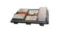
Figure 1: IRS Systementwicklung GmbH and GvA Leistungselektronik GmbH develop in close cooperation pulse power sources for up to 35kA.
Even in the event of a crash, it must be ensured that no dangerous voltage can reach the body of the vehicle. To this end, fuses are used that very reliably disconnect the energy storage system before live parts can bend and make contact. Assuming that a short circuit nevertheless occurs in the vehicle as a result of the crash, currents of several kiloamperes must be reliably separated. This is done, for example, with the aid of so-called pyro-fuses, which break the electrical connection with a small blast, similar to the ignition pills used in airbags, which are common in the automotive industry. Pyrotechnic fuses are a safety-relevant component and must therefore be tested intensively.
In order to prove the triggering behavior of such a component under simulated short-circuit conditions, a current source is required that can supply several kiloamperes of current for a few milliseconds. In addition, it must generate a realistic battery voltage of up to 1500V while the fuse is tripping.
IRS Systementwicklung GmbH and GvA Leistungselektronik GmbH develop in close cooperation pulse power sources for up to 35kA. This cooperation combines the long and solid experience of GvA for power electronics, high current design and system manufacturing and IRS for software, safety and measurement technology.

Figure 2: Simplified block diagram of the surge system
Key Facts
- Peak Currents up to 35kA
- Voltage Range up to 1500V
- Pulse Duration approx. 5ms @ 35kA
- Single or optional multi-pulse capability with IGBT technology
Applications
The surge testers from GvA and IRS can be used to test various switching devices in the automotive sector. The current focus is clearly on the separation of traction batteries in the event of a crash, but applications in the energy sector also have similar requirements.
On the one hand, the systems are used for design validation by manufacturers and testing institutes. In addition, random sample tests in production ensure the reliability of products with pyro-fuses.
Technical Description
Currents of 35kA at voltages of 1500V mean a peak power of more than 50 megawatts for short time. This amount of power may not be easily drawn from an even powerful industrial plant, not to mention from a standard laboratory socket outlet - the energy must be stored to be made quickly available at an instant.
The energy storage device is a capacitor, which is charged by power supplies up to a predefined voltage. The current pulse occurs when the capacitor is discharged via the device under test and an additional adjustable resistor in series. A semiconductor high speed high current switch defines the time of discharge, while mechanical contactors provide a safe disconnection during maintenance. The resistor and the voltage setting define the test current.
Energy Storage
Realistic battery voltages are already in the range of 400...800V today and will aim for 1500V in the future. Therefore capacitors with high dielectric strength must be used. Furthermore, the capacitors need high capacitances of more than two farads to keep the voltage within certain limits while the high pulse current flows. Such voltage-proof capacitors with high capacitance require a lot of space - between 3 and 8 cabinets, depending on the expansion stage.
To charge the capacitors up to 1500V within a few minutes, DC power supplies in the range of 10...50kW are used - depending on the required interval of firing. Furthermore, the power supplies must also be robust against possible overvoltages in the kilovolt range, which can be caused by inductive components. Finally, it is recommended to use units with mains feedback to efficiently feed back excess energy into the mains after the test.

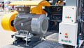
Figure 3: Huge capacitor banks from GvA buffer the necessary energy
Pulse unit
If the capacitor is charged, the current is fed into the test object via the pulse unit at a defined time. This is initially done via the fast semiconductor switch, which is available in two versions depending on the requirements:
Thyristor
- Single shot
- Reliable standard component
- Cost effective solution

Figure 3.1: Thyristor
IGBT Stack
- Multi-shot with on/off function
- complex IGBT array
- for any timing in µs resolution

Figure 3.2: IGBT Stack

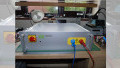
Figure 4: Semiconductor switches from GvA in comparison: cost-effective vs. complex timing

Figure 5: Current setting via resistance matrix and/or monitored jumper
While thyristor solutions can trigger a single current pulse at a precise point in time due to their DC voltage structure, the complex IGBT stack can be switched on and off at any time. This increases the flexibility of the system, e.g. to test closing switching elements with pulse current.
The test current is determined by the voltage applied to the capacitor and an adjustable resistance. Various solutions are in use in which configurable resistance matrices and, optionally, additional inductors simulate the internal resistance of the battery. If the resistance can be easily selected manually by the user via jumpers, it is possible to monitor this connection optically to exclude operator errors.
Measuring and control unit
The power section of the impulse system must be safely controlled and measurement data must be recorded in order to perform an analysis and evaluation later. Compact RIO from National Instruments is used in combination with IRS modules for precise timing and measurement. On the one hand, this platform enables powerful measurement and control technology in the µs range with a combination of processor with real-time operating system and FPGA. On the other hand there is a seamless connection to Windows systems to analyze the measurement data with familiar tools. While current and voltage pulses are recorded at high sampling rates, interference in the harsh environment of high magnetic fields must be suppressed. Hardware and software from IRS ensure that clean test results are available for further processing.

Figure 6: Time-precise control via fiber optic cables and analog measurement
The control of the power electronics (thyristor or IGBT) is galvanically isolated via IRS Compact-RIO optical interfaces. This ensures that the measuring system can be placed safely separated from the power electronics and that disturbing influences remain minimal. The measuring system is also galvanically isolated from the operating computer via fiber optics. Thus, the measuring technology and the control system in the operating room are additionally spatially separated from dangerous voltages.
User Interface
The system is controlled by an industrial PC with an IRS user interface, which makes it easy for the plant operator to create and execute test configurations. The status of the current source is always visualized and it is possible to process the measured data and waveforms for further analysis.
Safety engineering
Last but not least, safety is a critical issue in the operation of pulsed power systems. Safety controllers monitor the status of door contacts and interlocks, insulation and voltage monitors and control door interlocks, discharge contactors, load and ground switches to ensure that people are not endangered at any time. After all, touching voltages of up to 1500V is life-threatening. It must be ensured that the system is only in operation when all safety circuits are working without errors, doors are closed and all system states are plausible. Only when the energy has been almost completely dissipated, all accessible connections are automatically grounded and access to the test room is granted. At the same time, power supply units with mains recovery guarantee the efficient recovery of excess stored energy.

Figure 7: User software for easy configuration and visualization
But electrical hazards are not the only ones from which employees and visitors must be protected, because in the event of a fault, a test specimen can burst. It should be noted that more than 2 megajoules of energy are stored in a fully charged system.
If only 1% of this energy were to be converted into the movement of a mechanical component of a bursting test specimen, this part would get the force of a 12mm projectile. Spatial separation of the test specimen and safe software is therefore essential for the operation of such a system.

Figure 8: Safety control to avoid dangerous situations
A safety control always monitors the condition of the system as well as that of the higher-level test field - independent of the software used to operate the system.
Technical data
Different variants of surge current systems have been developed and built - depending on customer requirements. The following data represent the parameters of a fully developed version according to the current status. Smaller or larger variants can be supplied individually according to customer requirements.
| Min | Typ | Max | Unit | |
| Voltage range | 10 | 1500 | V | |
| Output current | 0.1 | 35 | kA | |
| Charging Power | 15 | 45 | kW | |
| Timing resolution (control and measurement) |
1 | µs | ||
| Pulse duration (@35kA) Depending on capacitance and voltage drop |
5 | ms |
This article originally appeared in the Bodo’s Power Systems magazine.