Facebook
 Google
 GitHub
 Linkedin
Totem-Pole PFC Topology: A Price-Performance Analysis
This article presents a price-performance analysis of the totem-pole power factor correction topology compared to other topologies.
This article is published by EEPower as part of an exclusive digital content partnership with Bodo’s Power Systems.
Industrial power supply applications like telecom and servers require cost-effective, efficient solutions. This article presents a price-performance analysis of the totem-pole (TP) power factor correction (PFC) topology compared to interleaved boost topology or TP-PFC with SiC MOSFET and synchronous rectification.
Efficiency and power density are critical considerations in industrial power supplies—particularly in telecommunication and server applications that operate 24/7 continuously. This has motivated power converter designers to develop topologies and use semiconductor technologies that enable smaller, lighter, and more powerful systems with lower ownership costs. The newer regulatory and energy labeling requirements have also set higher efficiency standards. The 80 Plus efficiency rating is fast becoming a widely accepted benchmark for power supplies. However, a PFC stage is essential to meet the regulatory requirements for harmonics standards. This may cause additional losses and increase system costs. To address this, PFC circuits must utilize converter topologies that provide optimal efficiency, performance, and cost-effectiveness. The CoolSiC Hybrid discrete IGBT in a bridgeless TP-PFC topology can meet the 80 Plus Titanium grade requirements, enabling power supply manufacturers to achieve higher efficiency while meeting regulatory requirements at a lower cost.

Image used courtesy of Adobe Stock
Power supply units typically use a two-stage design consisting of an AC-DC PFC stage and a DC-DC converter stage implemented in various configurations. Infineon’s EVAL_3KW_2LLC_CFD7 evaluation board includes a DC-DC converter stage utilizing a two-phase LLC configuration offering 98% efficiency over the entire load range and enabling reliable use of the half-bridge (HB) LLC topology with significant thermal benefits. The AC-DC PFC stage commonly uses the classic boost topology that requires only a single active power switch. However, the full-bridge diode rectifier stage preceding the boost PFC stage accounts for a significant portion of the total loss in the PFC stage. The interleaved boost PFC stage is employed at higher power levels to improve the power supply’s efficiency. Still, it requires more components, including multiple inductors and power switches, which increases system cost. To overcome the limitation of the boost topology, the bridgeless TP topology can be adopted. Using CoolSiC Hybrid discrete in this topology offers a highly efficient, cost-effective solution for high-power switched mode power supply (SMPS) applications.
650 V CoolSiC Hybrid Discrete
CoolSiC Hybrid discretes offer two significant advantages over conventional IGBTs equipped with silicon-based, co-packed diodes:
- Significantly lower the switching losses
- Improve the electromagnetic compatibility (EMC)
The CoolSiC Hybrid discrete doesn’t experience the diode’s reverse recovery, reducing losses in both the IGBT and diode. Its turn-on energy and switching slopes are almost independent of temperature. Measured data in Figure 1 indicates that the total switching energy can be halved compared to conventional IGBT co-packed with Si-diode.
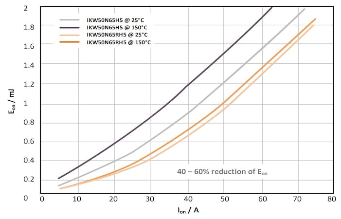
Figure 1. Comparison between the turn-on energy loss of the CoolSiC Hybrid discrete (IKW50N65RH5) and a conventional TRENCHSTOP 5 (IKW50N65H5). Image used courtesy of Bodo’s Power Systems [PDF]
Totem-Pole PFC With CoolSiC Hybrid Discretes
A bridgeless TP-PFC typically uses wide bandgap (WBG) devices in the high frequency (HF) leg and synchronous rectification, using silicon (Si) MOSFETs with very low RDS(on) in the low frequency (LF) leg to achieve higher efficiency. This results in a significant increase in the system cost. The continuous conduction mode (CCM) bridgeless TP-PFC requires low loss diode operation with fast reverse recovery performance of the switching device employed in the HF leg.
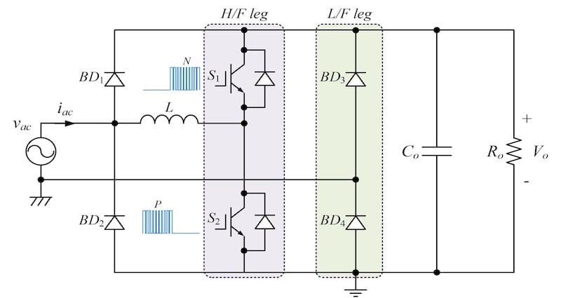
Figure 2. Bridgeless TP PFC with hybrid discrete devices and conventional rectifier diodes in the LF leg. Image used courtesy of Bodo’s Power Systems [PDF]
The CoolSiC Hybrid discrete IGBT combines the advantage of a SiC diode and a fast-switching silicon IGBT, offering significant switching performance improvement. It maintains the higher switching frequency required for smaller form factors and provides lower system costs than WBG device solutions. Moreover, as the IGBT in the CoolSiC Hybrid discrete is a unidirectional device, the reverse current flows through the SiC Schottky diode of the duo pack, simplifying the drive scheme, unlike a bridgeless TP-PFC that uses WBG devices and a synchronous rectifier with low RDS(on) Si MOSFET.
System Evaluation and Results
A PLECS simulation was performed to verify the performance of the CoolSiC Hybrid discrete in TP-PFC. The simulation results were as follows:
- Interleaved boost with fast-switching Si-IGBT and SiC diode: Higher power losses compared to the CoolSiC Hybrid discrete in a bridgeless TP-PFC
- TP-PFC with synchronous rectification using an 18 mΩ Si MOSFET in the LF leg and 48 mΩ SiC MOSFET in the HF leg: Significantly lower power losses, especially for light to medium loads
- Bridgeless TP-PFC with the CoolSiC Hybrid discrete in the HF leg and a 25 A conventional bridge rectifier (BR) in the LF leg: The semiconductor devices had lower total power losses compared to traditional interleaved boost PFC due to lower conduction loss in the rectifier diodes.
Figure 3 shows a comparison between the three scenarios.
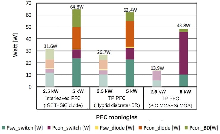
Figure 3. PLECS simulation of power losses in the semiconductor devices. Image used courtesy of Bodo’s Power Systems [PDF]
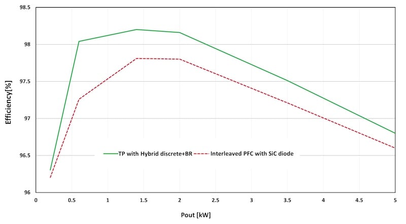
Figure 4. Efficiency of TP with CoolSiC Hybrid discrete. Image used courtesy of Bodo’s Power Systems [PDF]
The simulation results were verified through experimental measurements presented in Figure 4. Efficiency curves tested at a switching frequency of 65 kHz revealed that the bridgeless TP-PFC with CoolSiC Hybrid discrete offered improved efficiency over the entire load range compared to the conventional interleaved PFC, with the peak efficiency exceeding 98%.
Furthermore, a cost analysis indicated that a TP-PFC implemented with the CoolSiC Hybrid discrete might be 12% lower than a conventional interleaved PFC. It is because, in this case, the TP-PFC requires only a single inductor and two hybrid devices instead of two inductors, two SiC Schottky diodes, and two main switches needed for the interleaved boost PFC. The system costs of TP-PFC with a WBG solution are considerably higher due to the costly components.
Finally, an experimental analysis was performed on a complete system comprising a TP-PFC and a two-phase LLC connected in series. The measurements indicated the efficiency at 10, 20, 50, and 100% load to be 93, 94.28, 96.02, and 95.6%, respectively. This overall system efficiency measurement confirms that the TP-PFC meets the 80 Plus Titanium grade with a peak efficiency of over 96%, and its efficiency at full and light loads is well above the specifications for the 80 Plus Titanium grade.
Results: TP PFC Topology Price-Performance Analysis
When evaluating and validating the efficiency and cost benefits of a bridgeless TP-PFC topology using 650 V CoolSiC Hybrid discrete IGBTs, the results show the TP-PFC with CoolSiC Hybrid discretes and rectifier diodes offers better efficiency and lower system bill of materials cost compared to conventional interleaved boost PFC. It meets the 80 Plus Titanium grade with a peak efficiency of over 96%, providing the best price-performance ratio for industrial power supplies that operate continuously over an extended period.
This article originally appeared in Bodo’s Power Systems [PDF] magazine and is co-authored by Syeda Qurat ul ain Akbar and Jaeeul Yeon of Infineon Technologies Austria AG.