Facebook
 Google
 GitHub
 Linkedin
Current Measurement Methods that Deliver High Precision Power Analysis in the Field of Power Electronics
This article discusses the current measurement methods specifically on Direct Connection Method and Current Sensor method used in power analyzers.
Various power electronics applications demand high-precision power (current and voltage) measurement of such characteristics as the power conversion efficiency of power conditioners, the efficiency of inverters and motors, and reactor losses. This paper narrows the focus of the discussion to current measurement methods and introduces some of Hioki’s expertise as a longstanding developer of both current sensors and power analyzers leveraging proprietary technologies.
Current Measurement Methods
Power analyzers generally measure current by means of either the direct connection method (Figure 1[a]) or the current sensor method (Figure 1[b]). The following provides a detailed description of the characteristics of each approach.


Figure 1: Direct connection method (top) and current sensor method (bottom)
Direct Connection Method
In the direct connection method, current is measured by routing wires from the measured object to the power analyzer and connecting them to the instrument’s current input terminals. The measurement principle itself is extremely simple, with the advantage of enabling a power analyzer to be used to measure current on a standalone basis, making it the de facto method for many years. However, since the current wires must be routed over a long distance and the current input portion of the power analyzer must be inserted into the measured object’s circuit, the following disadvantages exist:
- Conditions differ from those that characterize actual operation
- There is increased loss due to the wire resistance of the long wires.
- Capacitance coupling occurs between individual wires and between wires and the ground, causing high-frequency leakage current to increase.
For example, concerning the effect described in ii) above, a 5-meter run using No. 6 AWG wire would have a wire resistance of approximately 6.5 m2. If the current under measurement were 30 A, the loss resulting from this wiring resistance would be 5.85 W. Although it is impossible to make any judgment concerning the magnitude of the loss based solely on this value, it would be too large to ignore for some measured power values.
In addition, when using the direct connection method, current usually is measured by means of a shunt resistance. This shunt resistance method suffers from the following disadvantages:
- When current flows into the shunt resistance, Joule heat proportional to the square of the current occurs in the resistance. As long as the Joule heat contributes to instrument loss, the self-heating will change the resistance value of the shunt resistance itself, which will further worsen the measurement accuracy.
- To limit this heating, a shunt resistance with a low resistance value is used. However, when a small shunt resistance is used to measure a large current, even slight inductive components cannot be ignored, which degrades the frequency characteristics.
Each of these disadvantages significantly worsens current and power measurement precision, dictating caution when measuring large currents.

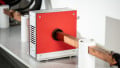
Figure 2: Self-heating of shunt resistance
Figure 2 illustrates the process of self-heating that occurs when a current of 20 A flows through a 2 m shunt resistance. For comparison purposes, a Hioki CT6862 current sensor with a rating of 50 A has been connected to the circuit. You can see that the temperature of the shunt resistance rises to about 50°C due to self-heating caused by Joule heat. By contrast, the current sensor is mostly unaffected by Joule heat and associated self-heating, and instrument loss and effects of the sensor’s own temperature characteristics on measurement precision are negligible.
As demonstrated by the above discussion, the direct connection method is well suited for the measurement of very small currents of about 1 A where the effects of the shunt resistance’s Joule heat are sufficiently small, for example measurement of the standby power of electronic devices or measurement of the power consumption of LED lighting.
Current Sensor Method
The current sensor method is a method for measuring current whereby a current sensor is connected to the wires on the equipment under test, and the output signal (current or voltage) from the sensor is input into the power analyzer.
The current sensor method can be used to measure a target in its operating state, and the almost complete lack of self-heating when measuring large currents means that there is no effect on measurement accuracy. The current sensor method is better than the direct connection method at measuring large currents of about 5 A or greater with a high degree of precision, and it is generally used in the power electronics field.
Figure 3 illustrates the approximate range of current values that can be measured with a high degree of precision and the associated general frequency band for both the direct connection method and the current sensor method. Please note that just because a value falls outside the range shown in the figure does not necessarily mean that it cannot be measured using the method in question.

Figure 3: Direct connection method and current sensor method: Approximate ranges of current values and frequency bands that can be measured at high precision *Exclusion from the ranges shown in the figure does not necessarily mean a value cannot be measured.
High-Precision Power Measurement using the Current Sensor Method
As described above, it is typical to use the current sensor method when measuring currents in excess of 5 A. While the current sensor method does not suffer from the same disadvantages as the direct connection method, there are nonetheless a number of precautions that must be borne in mind in order to measure current at a high level of precision. This section outlines those precautions.
Selecting a Suitable Current Sensor
High-precision, highly reproducible power measurement using the current sensor method presumes selection of a suitable current sensor. Specific selection criteria include the following two considerations:
- The current sensor’s rated current value must be appropriate for the magnitude of current to be measured.
- All frequency components of the current to be measured must fall within the current sensor’s measurable frequency band.
Furthermore, the following considerations should be borne in mind:
- The current sensor must provide a sufficient level of measurement accuracy that is defined across the entire measurable frequency band.
- All error factors, for example output noise, temperature characteristics, conductor position effects, external magnetic field effects, magnetization effects, and common-mode voltage effects for the current sensor, must be defined and sufficiently small in magnitude.
A sufficient level of caution is required when selecting a current sensor. In particular, concerning consideration iii), amplitude and phase accuracy for most current output sensors are only defined for DC and 50/60 Hz frequencies, and accuracy for other frequency ranges is provided only for reference purposes only.
It is important to note that high-precision current measurement using the current sensor method hinges on the availability of both current sensors and a power analyzer with an adequate level of performance.
Overall Optimization of Power Measurement Systems Including Current Sensors
Simply selecting a suitable current sensor as described above is not a sufficient condition for high-precision power measurement using the current sensor method. In addition, it is necessary to optimize the entire power measurement system, including the current sensor. Even if the current sensor detects the target current with an exceptionally high degree of precision, it will be impossible to measure the current with a similarly high degree of precision if the sensor’s output signal is degraded before reaching the power analyzer.

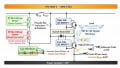
Figure 4: Typical power measurement system
Figure 4 illustrates a typical power measurement system that includes a current sensor. As described above, some current sensors generate current output, while others generate voltage output. Since current-output sensors are more commonly used than voltage-output sensors, this discussion will assume use of a current-output sensor.
The following conditions must be satisfied in order to ensure that the current sensor’s output signal can be transmitted to the power analyzer without degradation.
- A high-quality power supply must be used for the sensor, and it must be properly grounded.
- Coupling capacitance between multiple cables and between cables and ground must be low, and the noise resistance of the cables must be high.
- The power analyzer’s current inputs must offer good frequency characteristics with little heating and high insulation performance (high CMRR and low leak current). In addition, the instrument must provide high noise resistance, and it must be properly grounded.
In general, power is measured with current sensors, a power supply to drive the sensors, and a power analyzer that are all from different manufacturers, and the cable type as well as wiring method are dependent on the user’s discretion. In light of this, it goes without saying that it is extremely difficult for current sensor manufacturers, power analyzer manufacturers, and sensor power supply manufacturers to guarantee that all of the conditions listed above will be satisfied for any given setup, that the current sensor’s output signal will reach the power analyzer without suffering degradation, and that the target current will in fact be measured at a high level of precision.
On the other hand, Hioki is the only test and measurement instrument manufacturer in the world that independently develops and designs both current sensors and power analyzers, giving us the ability to deliver all of the components necessary for building a complete power measuring system.
Hioki power measurement systems provide the following features:
- We use voltage-output current sensors for which accuracy has been defined across the entire measurable frequency band.
- Power analyzers’ current inputs are designed specifically for use with voltage-output current sensors, and both sensor output voltage levels and input voltage levels for power analyzers’ current inputs have been optimized.
- Power analyzers have a built-in sensor power supply that drive the sensors with power whose quality is identical to that used at Hioki when determining accuracy. By applying a number of meaningful design features such as using the same ground for the power analyzer and the sensor power supply and eliminating the causes of ground loops, we have vastly improved measurement precision and reproducibility.
- In addition to using shielded wires to carry sensor output as a way to counteract noise, Hioki has built in functionality for adjusting sensor output gain to compensate for the minuscule voltage drop-off caused by the cables.
Furthermore, Hioki subjects current sensors and power analyzers together to evaluations of measurement accuracy and noise testing both in-house and by third-party certification authorities.
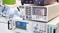
Figure 5 portrays a power measurement system consisting of Hioki current sensors (CT6862, CT6863, 9709, CT6841, CT6843, and 3274) and a power analyzer (PW6001) undergoing immunity testing by a third-party certification authority.
By carefully designing each individual element and qualifying them in combination in order to optimize the system as a complete set, Hioki is poised to deliver a world-class power measurement system to our customers.

Figure 5: Immunity testing of a Hioki power measurement system by a third-party certification authority
Conclusion
In addressing high-precision power measurement as required in a variety of settings in the power electronics field, this paper focused on current measurement methods and briefly introduced some of Hioki’s expertise as a longstanding developer of both current sensors and power analyzers leveraging proprietary technologies. Due to the constraints of space, it was unable to cover, or was only able to mention in passing, many of the more detailed aspects of this subject. Hioki looks forward to providing similar information to readers in the future.
About the Authors
Hajime Yoda works as the Assistant Chief Engineer, Hiroki Kobayashi works also as an Assitant Chief Engineer and Shinya Takiguchi works as a Senior Staff at Hioki E.E. Corporation, A Japanese electrical measuring equipment developer and manufacturer based in Ueda, City, Nagano Prefecture. The company was first established in June 1935, and registered as Hioki E.E. on January 5th, 1952
This article originally appeared in the Bodo’s Power Systems magazine.