Facebook
 Google
 GitHub
 Linkedin
Tiny MicroModules with PFM
A warehouse provides a prime example of an industrial environment where there are numerous electronic applications and rail voltages. Complex conveyor systems with their many sensors, actuators and control units is just one example of the countless applications that are implemented in industrial warehouses. Each of these applications has its own requirements in terms of supply voltage, current and installation volume.
For example, a surveillance camera with its microcontroller unit and image sensor requires 3.3 V and currents in the ampere range. The cameras are installed in various positions that often do not have a direct connection to the DC bus and have very limited installation space (system 1). Industrial grade inductive sensors are usually connected directly to the DC bus (system 2). Their geometrical design is similar to a metric screw, e.g. M12, in which the sensor and the evaluation electronics are integrated. An example industrial environment applications structure could look like the one shown in figure 1.
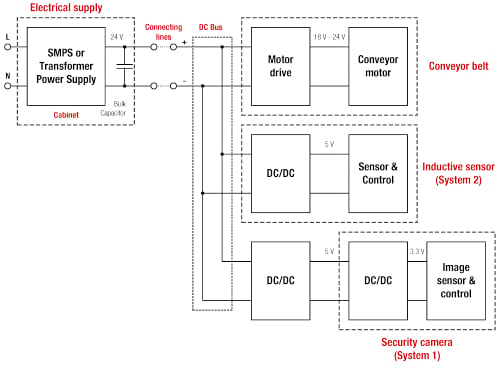
Figure 1. Block diagram of a warehouse application. Image used courtesy of Bodo’s Power Systems
All the applications described so far have one thing in common, they have to be realized in a confined space. Tight space, by definition, requires tiny DC/DC converters which have excellent thermal performance. This article digs deeper into the challenges that arise for the power supply of space-constrained applications regardless of whether they are supplied via an upstream DC/DC converter or are connected directly to the DC bus and how they can be overcome.
| Challenge | Solution |
| Restricted board space and high power demands | Power modules offer very tiny solution sizes and high power densities |
| Limited battery life | Ultra low quiescent current and high efficiency |
| Thermal sensitivity | High efficiency |
| Long, reliable product lifetime | Mature well proven technology (synchronous buck converter with reliable packaging approaches qualified to the highest standards) |
| Ultra low EMI radiation | Integrated, shielded inductor; optimized substrate layout; short current loops |
| Line rejection | Tight output voltage tolerance and low ripples |
| Unexpected dynamic load changes | Fast transient response |
| Unexpected dynamic supply changes | Ultra wide / robust input range |
Common challenges for space constrained DC/DC converters
Independent of the system setup being in a space constrained application environment, you will always face the same challenges when designing the DC/DC converter.
To realize the solutions with a DC/DC converter we need to better understand the design process of the converter.
Tiny and compact MicroModules – Advantages for the use of power modules during design-in
Space constrained inherently means the available design space for the system is limited as illustrated by the security camera application. Therefore, the optimum design is characterized by the best usage of that available system volume to meet the power demands of the application.
The design of a discrete converter requires at least the following steps:
• Design of the DC/DC converter itself
· Select the topology
· Select the controller IC
· Calculate and select the power parts (MOSFET, Diode, Inductor)
· Calculate and select the input and output capacitors
• Test bench development
• Optimization for stable regulation over the entire input/output voltage and load current range
• Layout routing for good EMI and thermal performance
• Validation of the overall design for easy manufacturing
• Pre compliance tests for EMI and safety
• Logistic chain and production security
All of the discrete DC/DC converter design steps mentioned before have already been performed in a MagI³C power module. This fact allows designers to simply select a module based on the electrical specifications of the application and therefore get rid of all the above mentioned design steps. Therefore, a power module enables design engineers to speed up the process of designing a power supply for their system compared to a conventional discrete DC/DC converter.
The use of a power module from the VDMM family shortens the overall time to market while saving design resources. The DC/DC power modules offer a high power density solution designed to offer the most power for the least space.
Space Constrained Applications can use MicroModules to supply the 3.3 V & 5 V rail
To get a better overview of the requirements of an industrial space constrained application we take a closer look at the example of a security camera system with its functional units.
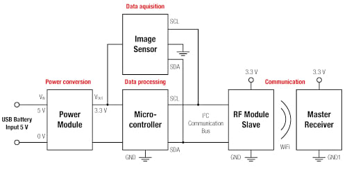
Figure 2. Block diagram of a security camera application. Image used courtesy of Bodo’s Power Systems
Description of the application:
The application consists of an energy source, a DC/DC converter, an image sensor, an MCU unit and WiFi communication devices. The DC/DC converter regulates the 5 V that comes from the battery or the USB port to 3.3 V, providing a stable regulated power to the MCU. The MCU processes data, initiates follow-up actions and sends commands to the sensor and the WiFi communication module. The RF Module (slave) then sends the data from the image sensor via WiFi to the master receiver unit. From there the data will be processed and visualized on a display.
If we now compare the challenges we have found until now with the requirements of this application we will see that:
• A battery supplied application needs ultra-low quiescent current and high efficiency
• The thermal sensitivity of the battery requires a DC/DC converter with high efficiency
• The space constrained package needs an ultra-low EMI radiation DC/DC converter that has to be realized with an integrated, shielded inductor, optimized substrate layout, and short current loops
The next step is to evaluate the basics of the switching behaviour of the DC/DC power module, which is the solution for most of the mentioned challenges.
Importance of efficiency for space constrained DC/DC converters Why do we need different switching behaviours?
Battery powered applications like portable devices do not always operate under full load conditions. If we look at a measurement application, there is a higher current demand during measuring and a lower one between the measurement instances.
Therefore, the power management has to be flexible enough to offer the best performance during each load situation.
Two different load situations are present:
• Light load – application works in idle or standby mode at reduced energy consumption
• Heavy load – application works under nominal conditions at
Efficiency and switching behaviour
Figure 3 and Figure 4 show the efficiency of the 1.2 A MicroModule, WE MagI3C Power Module 171010550, as an example of the different load situations discussed above. In figure 3, we see the “typical” behaviour that we expect from standard buck converters operating in pulse width modulation (PWM) mode. Forced PWM mode is widely used and this mode is present in the majority of industrial power supplies. This mode is satisfactory for this type of application as they work in heavy load conditions for the majority of their operating lifetime. However, applications like sensors have a different load situation. Here, the light load condition is the predominant operating situation. Therefore, the switching behaviour has to be modified to perform optimally during this load situation.
Pulse frequency modulation (PFM) mode clearly offers higher efficiency values as the load current decreases. This supports a longer lifetime of the battery in battery powered devices.
Forced PWM Mode:
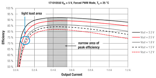
Figure 3. Forced PWM mode efficiency in dependence of different load conditions, WE MagI3C Power Module 171010550. Image used courtesy of Bodo’s Power Systems
PFM / PWM Mode:
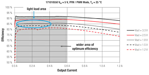
Figure 4. PFM / PWM mode efficiency, WE MagI3C Power Module 171010550. Image used courtesy of Bodo’s Power Systems
If we take the grey curve where Vout = 1.8 V, the transition between PFM mode and PWM mode is around 400 mA. The point at which the transition happens depends on the output voltage and the input voltage.
The PFM mode
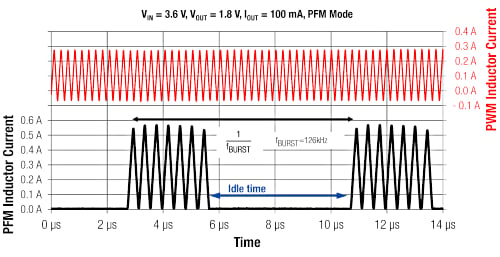
Figure 5. Comparison between PWM and PFM mode, WE MagI3C Power Module 171010550. Image used courtesy of Bodo’s Power Systems
Description of the switching behaviour:
Figure 5 compares the inductor current of the module WE 171010550 during PWM and PFM behaviour. The inductor current switches in bursts when operating in PFM mode. Both the load and the output capacitor are supplied with energy during each burst. During the idle time (the time between two burst actions) both switches, the high side and the low side, are switched off. This leaves the output capacitor to supply the load current entirely by itself. Therefore, the energy consumption of the module between two burst actions drops dramatically until the feedback system triggers the next burst action. In turn, the efficiency in PFM mode is significantly higher compared to that of traditional PWM mode due to lower switching losses. The idle time is inversely proportional to the load current, i.e. if the load current increases, the time between the burst actions decreases. The module switches back from PFM to PWM mode when the idle time approaches zero, returning to constant switching behaviour at the default switching frequency of 4 MHz.
The peak inductor current during PFM mode is higher than in PWM mode, allowing the same amount of energy to be delivered to the load in a fixed period of time while decreasing the losses generated within the converter. During the idle time in burst mode the module produces no losses compared to the PWM mode.
Output voltage ripple:
If the output voltage is higher than a certain value both switches remain off. During the idle time only the output capacitor supplies the load current, meaning the output voltage will drop. When the output voltage drops to a certain level the next burst cycle starts. The resulting value of the ripple depends on the threshold value that is set internally by the controller IC. The output voltage ripple during PFM mode can be reduced by simply increasing the output capacitor. The maximum value for the output capacitor can be found in the corresponding datasheet of the power module.
Dimensional scaling of Power Modules supplying the 3.3 V & 5 V rail
The phrase ‘space constrained’ does not mean that there is only one DC/DC power module that will fit every application. Each application has its own power supply requirements. To address the numerous possible demands of space constrained applications, a family of DC/DC power modules is needed. Each family member has its specialization, allowing for flexibility based on various design and production parameters.
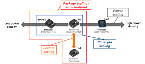
Figure 6. Dimensions of scaling, variety of different designs, WE MagI3C Power Modules. Image used courtesy of Bodo’s Power Systems
Package scaling / same footprint (red)
Due to the pin and package compatibility, the designer has the freedom to evaluate the application using either 600 mA or 1 A by simple changing the power module. The layout stays the same in both options. With a minor change in layout to accommodate the power good feature of the WE MagI3C 171010501 module, a third module can be seen as nearly pin compatible.
Power scaling (grey)
Today, applications are constantly demanding higher power levels with decreasing board space. For rising power demands, the designer can choose to get from 600 mA up to 1.2 A in tiny form factors.
Pin to pin scaling: (blue)
For a 100% one to one replacement the designer can choose between the 600 mA 171960501 and the 1 A 171010502 WE MagI3C power modules.
Feature scaling: (orange)
Depending on the specific needs for an application’s power supply, the designer can choose between output voltage status monitoring with the 171010501 WE MagI3C power module and active efficiency control with the 171010502 WE MagI3C power module.
MicroModule for direct 12 V & 24 V DC Bus connection
So far, however, we have only looked at an application that is supplied by low rail voltages. The supply for the DC/DC is assumed here as a stable pre-regulated supply voltage. This means that between the standard 24 V DC bus and the low rail voltage exists another converter which converts the high bus voltage to the application voltage (e.g. 5 V). To evaluate the requirements for DC/DC converter that is directly connected to the 24 V bus we will take a look at an application example of an inductive sensor.
Inductive sensors for industrial environments used to detect metal objects are supplied with 24 V input and require 5 V for their internal logic. There are two features that are most important for this type of power module. One decisive criterion here is the robustness of the power module to short-term changes in the 24 V input voltage, so-called transients. Second, the DC/DC has to be very tiny to fit into an M12 threaded tube while maintaining excellent efficiency to ensure good thermal performance.
Classically, the 24 V DC bus in the industrial environment is specified to 19.2 to 30 V according to IEC 61131-2 Industrial-process measurement and control - programmable controllers. In reality, however, various factors play a critical role in how much the 24 V deviates from this tolerance range. For example, if the 24 V supply line is laid parallel to the control line of a frequency inverter, the pulses are capacitively coupled and the 24 V oscillates in the pulse pattern of the frequency inverter. Similarly, a DC motor connected to the rails will also cause a brief increase in the 24 V bus voltage during braking or load shedding. These disturbances can quickly leave the normal range and irreparably damage the connected applications. Figure 7 shows the 24 V rail with its tolerances.
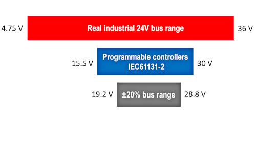
Figure 7. 24V bus with tolerances. Image used courtesy of Bodo’s Power Systems
To ensure good thermal performance we can take the knowledge from the DC/DC for low voltage input rails as it is also valid for this type of DC/DC.
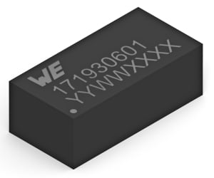
For all those challenges on the input and output side due to its ultra wide input voltage range as well as for the tiny package with good thermal performance and an adjustable output voltage the MicroModule (171930601) offers the perfect solution.
Characteristics:
• Ultra wide input voltage range 3.5 to 36 V
• Ideal for space constrained applications
• Very low profile LGA-8 package
• Power good indicator to show VOUT status
• Low conducted and radiated EMI (compliant to EN55032 class B / CISPR-32)
• Three solder cycles supported
Applications:
• HVAC and building control
• Supply for IoT applications
• Sensors
• Point-of-Load DC-DC applications from 24 V, 18 V, 15 V, 12 V, 9 V, 5 V industrial rails
In summary power modules like the MagI3C series provide proven, tested, reliable and compact solutions to space-constrained and budget-constrained projects. They incorporate the latest advancements in technology like the combination of PFM/PWM modes which provide better efficiency at lighter loads and optimal efficiency over the entire load range. This makes them ideally suited to applications that are battery powered. The proliferation of IoT sensor applications, that read and transmit data periodically are a prime example of an application that benefits from the automatic transition between PFM and PWM modes due to an active and a quiescent load state.
This article originally appeared in Bodo’s Power Systems magazine.