Facebook
 Google
 GitHub
 Linkedin
Using a Modular Power Stage to Rapidly Prove the Design of a 14 kW, 800 V LLC
This article shows a modular power stage from Converter Technology that can rapidly prove the design of a 14kW, 800V LLC topology
The LLC topology has been gaining favor recently as a possible topology for electric vehicle (EV) chargers in conjunction with several papers at this year’s IET PEMD event. Evaluating some of the performance trade-offs in the resonant stage design of magnetic components at an early stage is useful. This article shows a modular power stage from Converter Technology that can prove the design of a 14 kW, 800 V LLC.
The Converter Technology Hardware Stack™ modular platform provides an ideal way to investigate the operation of an LLC in the 10 kW – 15 kW region. It provides a 1.2 kV, 25 mΩ Silicon Carbide (SiC) 3-phase full-bridge module, with an integrated protection stage (OVP, OCP etc.) plus a powerful, Delfino™, 32-bit micro-controller. The controller can configure the system to use one, two or three legs of the module and provides a platform upon which complex (or simple!) control strategies may be implemented and investigated.
The design focus can now be solely on the system performance rather than the details of the PCB design, controller selection and the like, which greatly reduce the time and effort needed to validate a system concept and prove the magnetic design for example. Figure 1 shows the Hardware Stack™ power stage (left) with the output rectifier stage (bottom right) and the resonant inductor, capacitor and transformer (top right).
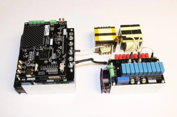
Figure 1: Hardware Stack™ based LLC
The LLC Topology as a DC Transformer
For simplicity, the system was run as a DC transformer, that is open loop and operated at a fixed frequency. One of the key features of the LLC is that operation at the series resonant frequency, fS, decouples the output load regulation from the resonant behavior thus giving minimal voltage variation without the complexity of a control loop.
With a 1:1 turns-ratio on the transformer as implemented here, this could be used as an isolating stage after an AFE or, by changing the turns-ratio of the transformer, to provide a semi-regulated output at a more suitable voltage for the load.
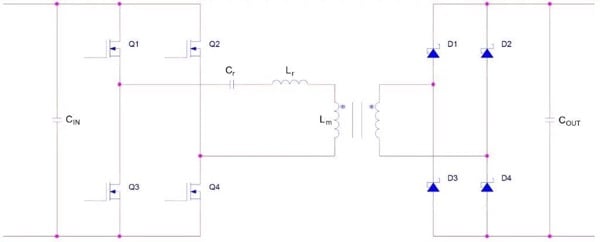
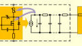
Figure 2: LLC Power Stage
With reference to figure 2, the series resonant frequency is a function of the resonant inductance, Lr, and the resonant capacitance, Cr, and is independent of the magnetizing inductance, Lm. Moving the switching frequency, fSW, away from fS shows the gain increasing for lower frequencies and reducing for higher ones, the relatively shallow slope above fS highlights the control range issue.
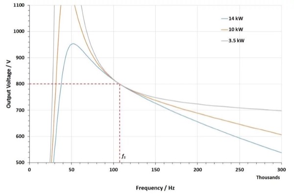
Figure 3: LLC Gain curves
The shape of the resonant curve shown in figure 3 is controlled not just by Lr, Cr, and Lm but also by the turn’s ratio and the load impedance. With many permutations possible, a means to rapidly check the preliminary design is advantageous.
A basic specification of 800 V input to 800 V output at 14 kW formed the basis of the design. The operating frequency was initially targeted at 100 kHz with the intention of further investigating operation at higher frequencies. A limitation of the DC supply meant that testing could only be conducted up to 600 VIN and thus 600 VOUT; this has minimal effect on the operation of the LLC.
Targeting fS = 100 kHz, and based on a load impedance, RL, of 30 Ω, and Q of ≈2; CS, LM, and LS were calculated as 100 nF, 160 µH and 22 µH. This gave fS at 107 kHz, an LM/LS ratio of 7.3.
Both the transformer and inductor were constructed using Litz wire on dual E70/30/32 bobbins with 3F3 ferrite and gapped to achieve the desired inductance. It is worth noting that these are not necessarily the optimum designs, the idea was to highlight the speed with which a prototype could be constructed.
For the resonant capacitor, we need a specific capacitance and a minimum ripple current capability. Furthermore, the resonant frequency of the capacitor needs to be above fSW. The resonant capacitor was thus constructed using a 2x9 array of metalized polypropylene capacitors to achieve a capacitance of 100 nF, a ripple current capability ≈27 ARMS at 200 kHz and a resonant frequency in the region of 2 MHz.
Switching Waveform Performance
Looking at the switching waveform shown in figure 4, it can be seen that the system is operating almost exactly at fS, it is actually slightly above, at 108 kHz, and a very small step can be observed in the current waveform. The voltage transitions show full ZVS operation, the rounded corners highlighting the non-linearity of the node capacitance. Varying the frequency either side of fS showed a small change in efficiency as well as the expected change in output voltage.

Figure 4: LLC Switching waveform
Varying the output load showed minimal variation in VOUT, less than 6 V difference between 5 A and 20 A load, and the current at the switching transition is independent of load ensuring ZVS.
The efficiency varies with the load as shown in figure 5; the drop in efficiency at higher power is unexpected but likely related to the magnetic and rectifiers. This has not been investigated so far, but it would be expected that the efficiency should remain in the 98% region up to full power, indeed further investigation may yet yield higher efficiency all around.

Figure 5: Efficiency vs Output Power
On the Subject of Efficiency
In Figure 6, the difficulties in measuring the effects are evident in the error bars shown in the efficiency curve and even more pronounced when the power dissipation is considered. The uncertainty in the power measurement has been calculated at around ±0.23% giving an efficiency uncertainty of ±0.45%.
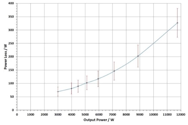
Figure 6: Power Loss vs. Output Power
Taking the difference between two large values with small errors leads to a relatively large error in the result; this translates into an uncertainty in the dissipated power of around ±16% to ±24%. In other words, the possible power loss could span a near 2:1 range! At 11.8 kW, the power dissipation could be between 273 W and 381 W, not insignificant. This is based on the measurement errors being completely uncorrelated. Clearly, for precision measurements, techniques such as calorimetry are necessary.
In order to achieve even 10% accuracy on the dissipated power in a 98% efficient system requires that the input and output power are measured to better than 0.2% accuracy. Figure 7 shows how the measurement accuracy affects the accuracy of the calculated power dissipation.
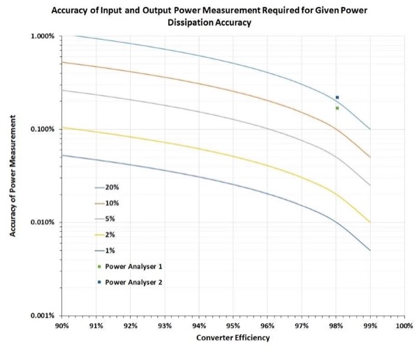
Figure 7: Power dissipation accuracy
Based on thermal measurements and modeling (using PLECS) the actual efficiency and power loss are much closer to the measured value than the uncertainty in the measurements indicated and 98% is not unreasonable. Furthermore, since the testing was conducted at 600 V, the efficiency at 800 V, which is the real target, would be even higher due to reduced I2R losses.
Conclusion
The LLC provides a very clean switching environment, and soft switching provides a very efficient converter that should also minimize the EMC burden, while there is some work required to determine the best fit for the resonant components. It has demonstrated itself to be a relatively straightforward topology to work with; however, it will introduce complications when transient conditions are to be investigated.
Implementing a multi-kW system using the modular building block approach characterized by the Hardware Stack™ was both quick and straightforward. A working converter was running within 1 – 2 weeks dictated mainly by the time to obtain cores etc. Within this timeframe, a 98% efficiency is very encouraging, and the platform provides a solid base upon which to refine the magnetic/resonant design and determine the specification for the power devices, heatsink etc. (Note the heatsink for Hardware Stack™ is deliberately excessive and additionally provides a mechanical base).
Further work on the LLC is intended to look at the impact of increased switching frequency amongst other things. Equally Hardware Stack™ will be used to investigate further power stages such as an AFE, inverter etc.
About the Author
Anthony Middleton works as the Senior Designer at Converter Technology, Pangbourne, UK where he is responsible for designing power supplies from a few watts to 10's of kW, GaN and SiC development using dsPICs and C2000s for digital control and more. He received an IEEE Certificate in Wide Band Gap Circuit Optimisation and Performance Comparison. He is also skilled in the field of power management, electronics as well as power electronics. He earned his Bachelor's Degree in Electronic and Electrical Engineering and his Master's Degree in Space Engineering both at the University of Surrey located in Guildford, England.
This article originally appeared in the Bodo’s Power Systems magazine.