Facebook
 Google
 GitHub
 Linkedin
Understanding Frequency, Phase Angle and Wavelength in AC Systems
In this article, learn what is meant by frequency, phase angle, and wavelength and how to find a phase relationship between two sine waves.
Frequency is the number of cycles per second in an AC sine wave. The Hertz is the international unit of frequency equal to 1 cycle per second. Frequency is also used to describe the power used in residential, commercial, and industrial facilities. For example, most power in North America operates at 60 Hz.
A wavelength (λ) is the distance covered by one complete cycle of a given signal frequency as it passes through the air. There is an inverse proportion between the wavelength of a signal and its frequency. Signals of different wavelengths fall into different frequency categories, including radio waves, infrared light waves, visible light waves, X-ray light waves, and cosmic waves.
Phase (φ) is the time relationship of a sine wave to a known time period. Sine waves often depict the relationships between two or more signals. In-phase sine waves have peak values and baseline crossings that occur simultaneously, while out-of-phase sine waves have peak values and baseline crossings at different times.
Frequency
Consider Figure 1, which illustrates the sine wave output from an AC generator. It has been shown that when the conductors in the simple generator are rotated through one complete revolution, the output voltage goes through one complete cycle of sinusoidal change. The time taken for one cycle of change (from zero volts through +Em, zero, and -Em back to zero again) is referred to as the time period of the waveform and is designated as T (see Figure 1). If T=1 s, the waveform has a frequency (f) of 1 cycle per second or 1 hertz (Hz).
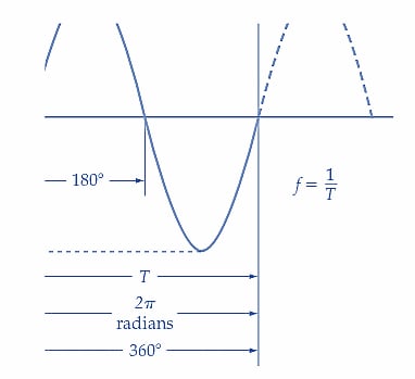
Figure 1. One cycle of a sinusoidal voltage waveform. The instantaneous voltage (e) increases from zero to Em, then decreases through zero to Em, and returns again to zero. Image used courtesy of Amna Ahmad
A waveform's frequency is always calculated by inverting the time period.
\(f=\frac{1}{T}\) (1)
where T is in seconds and f is in Hertz.
The frequency for domestic and industrial AC supplies across North America is 60 Hz [see Figure 2]. In electronics, the AC waveforms’ frequencies range from zero (in the case of DC) through kilohertz (kHz) and megahertz (MHz).
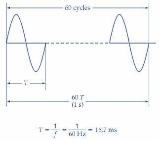
Figure 2. The waveform’s frequency is measured in cycles per second or Hertz (Hz). Image used courtesy of Amna Ahmad
Phase Angle
For one complete revolution, the conductors in the simple generator rotate through 360°. If the angle of rotation of the conductors is measured in radians instead of degrees, one complete revolution represents 2π radians. As T is the time period in seconds (or time for one complete revolution), the angle through which the conductors move in 1 s is given by,
\[Angular\,Velocity=\frac{1}{T}\frac{revolutions}{second}\]
\[=\frac{360}{T}\frac{degrees}{second}\]
Or,
\[Angular\,Velocity=\frac{2\pi}{T}\frac{radians}{second}\]
And the phase angle (θ) of the generated voltage at any instant t1, t2, t3, … measured from t =0 is,
\[\theta=\frac{2\pi}{T}\times t\,radians\]
Also,
\[\theta=\frac{360}{T}\times t\,degrees\]
Because f=1/T, the phase angle equations can be rewritten,
\[\theta=360\,ft\,degrees\]
And,
\[\theta=2\pi\,ft\,radians\]
Or,
\[\theta=\omega t\,radians\]
Where ω is the angular velocity in radians/s (i.e., ω=2πf).
Now, the AC waveform can be represented by the following equation:
\(e=E_{m}sin\omega t\) (2)
Also,
\[e=E_{m}sin(360ft)°\]
Figure 3 illustrates the use of Equation 2.
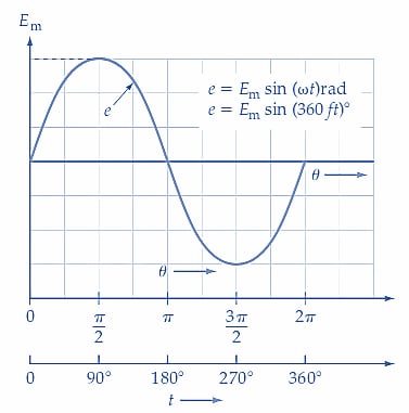
(a) e can be determined from ωt or 360 ft
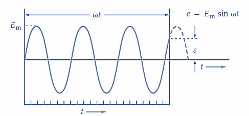
(b) e can be determined at any point in a waveform containing many cycles
Figure 3. The phase angle of a waveform can be expressed in degrees or radians, and either can be used in calculating instantaneous level. Image used courtesy of Amna Ahmad
Example 1
An AC waveform with a frequency of 1.5 kHz has a peak value of 3.3 V. Calculate the instantaneous voltage levels at t1=0.65 μs and at t2=1.2 ms.
Solution
Equation 2,
\[e=E_{m}sin2\pi ft\]
At t1,
\[e=3.3V\times sin(2\pi\times1.5kHz\times0.65\mu s)rad\approx20.2mV\]
At t2,
\[e=3.3V\times sin(2\pi\times1.5kHz\times1.2ms)rad\approx-3.1V\]
Phase Difference
Four different waveforms are illustrated in Figure 4. Waveforms B, C, and D have smaller amplitudes than waveform A. Waveform B goes through its cycle of change exactly at the same time as waveform A, so the two are said to be in phase with each other.
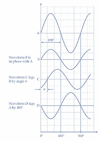
Figure 4. In-phase and out-of-phase sine waves. Waveform B is in phase with waveform A. Waveform C lags waveforms A and B. Image used courtesy of Amna Ahmad
Waveforms C and D are out of phase with waveforms A and B. Because waveforms A and B commence their cycles ahead of C by an angle (degrees or radians), A and B are said to lead C by . Alternatively, waveform C may be said to lag waveforms A and B by . The angle may also be referred to as the phase difference between the waveforms. Waveform D lags A and B by 180° and is said to be in antiphase to A and B because it is at its negative peak when A and B are at their positive peak levels, and vice versa.
Wavelength
The wavelength of an AC waveform depends on its velocity. In the case of radio waves, the velocity is the speed of light, which is,
\[c=3\times10^{8}\frac{m}{s}\]
For voltage waves moving along widely spaced conductors, the transmission speed is also 3 *108m/s. When the conductors are close together, the velocity depends on the insulation employed. Figure 5 (a) shows a pair of long conductors connected to a generator, and parts (b), (c), (d), and (e) show the instantaneous voltage levels at points on the conductor as the terminal voltage changes.
In Figure 5(b), e1 represents the initial or zero level of a voltage waveform at the beginning of a long conductor. A fraction of a second later, in Figure 5 (c), e1 has traveled some distance along the conductor, and the instantaneous level of the voltage at the generator terminals has changed to e2. Both e1 and e2 are traveling along the conductor at a velocity of 3 *108m/s. In Figure 5(d), the voltage at the generator terminals has changed to e3. By the time the generator terminal voltage has gone through one complete cycle [Figure 5(e)], e1 has been moving along the conductor for the time period T. So, during one complete cycle, the distance traveled by e is,
\[distance=c\times T\,meters\]
\[=\left(3\times10^{8}\frac{m}{s}\times T\right)m\]
This distance represents the wavelength (λ) of the alternating voltage. The equation for wavelength is,
\[\lambda=c\times T\]
Or,
\(\lambda=\frac{c}{f}\) (3)
Where λ is wavelength in meters, c is the velocity of light in m/s, and f is the frequency of the waveform in Hertz.
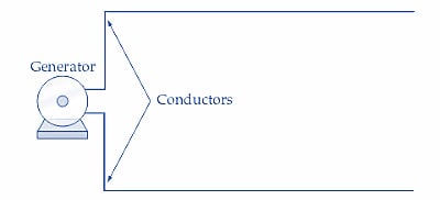
(a) Generator with two long conductors
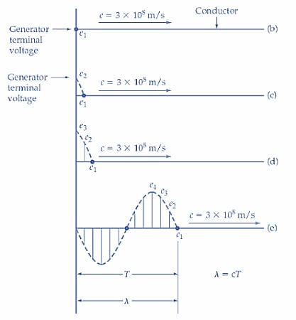
Figure 5. An alternating voltage wave moves along widely spaced conductors at the speed of light (c = 3 108 m/s). The time period of one cycle is T = 1/f, and the wavelength is = cf. Image used courtesy of Amna Ahmad
Example 2
Determine the wavelengths of 60 Hz and 1 MHz alternating waves. Calculate the frequency of a voltage that has a wavelength of 33 m.
Solution
For 60-Hz,
Equation 3,
\[\lambda=\frac{c}{f}=\frac{3\times10^{8}\frac{m}{s}}{60\,Hz}=5\times10^{6}m\]
For 1 MHz,
\[\lambda=\frac{c}{f}=\frac{3\times10^{8}\frac{m}{s}}{1\,MHz}=300\,m\]
From Equation 3,
\[f=\frac{c}{\lambda}=\frac{3\times10^{8}\frac{m}{s}}{33\,m}=9.09\,MHz\]
Key Takeaways of Alternating Current
Alternating current (AC) is the voltage found in residential, commercial, and industrial locations. The direction of current flow in an AC system reverses periodically. Terminology commonly used with AC circuits includes phase angle, frequency, wavelength, and phase difference. These terms are particular to AC systems and are used when designing and troubleshooting AC electrical systems.
Featured image used courtesy of Adobe Stock