Facebook
 Google
 GitHub
 Linkedin
Understanding AC Voltmeters With PMMCs
This article examines the behavior of permanent magnet moving-coil instruments connected to AC, where the polarity affects deflection and presents the principle of rectification, transforming AC into unidirectional pulses using rectifiers, and its application in AC voltmeters to accurately measure root mean square values for pure sine waves.
This article comprehensively explains the permanent magnet moving coil (PMMC) instrument's behavior on alternating current (AC). The PMMC instrument, being polarized, requires a correct polarity connection for accurate deflection. When connected directly to AC, particularly at low frequencies, the pointer moves in correspondence with the current peaks. However, due to limitations in the instrument's movement capabilities, it settles at the average level of the AC passing through the windings, often averaging to zero at typical AC frequencies like 60 Hz. The article further explores rectification using semiconductor diodes to convert AC into unidirectional pulses, enabling accurate measurement of root mean square (rms) values—a crucial aspect in precise AC voltage measurements. Additionally, the article delves into designing an AC voltmeter calibrated to indicate rms values, taking into account multiplier resistance calculations based on given parameters. The limitations of using rectifier voltmeters with non-sine waveforms are also explained, emphasizing the importance of accurate waveform consideration in AC measurements.
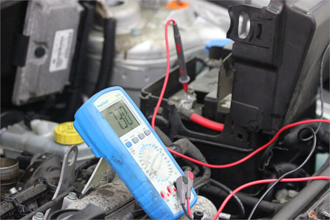
Image used courtesy of Pixabay
In the case of AC voltmeters, rectification plays a pivotal role. A rectifier, often a semiconductor diode, is employed to convert AC into unidirectional pulses. Understanding these principles is fundamental for accurate voltage measurement in AC circuits.
PMMC Instruments
The permanent magnet moving-coil instrument used to measure rectified AC is polarized, meaning the terminals of the instrument are identified as plus (+) and minus (-), and for correct deflection, the meter must be connected with that polarity. When incorrectly connected, the pointer attempts to deflect to the left of zero (i.e., off-scale). Now consider what occurs when a PMMC instrument is connected directly to an alternating current source, as shown in Figure 1(a). For the illustration showing the instantaneous pointer position [Figure 1(b)], it is assumed that the frequency of the alternating current is very low, around 0.1 Hz. As the current level increases positively from zero, the meter pointer moves to the right until it indicates peak current. Then, the pointer returns to zero again as the current level drops. When the current direction reverses during the second half-cycle of the waveform, the meter attempts to deflect to the left, which, of course, is impossible. Consequently, the pointer remains at (or just below) the zero mark during the negative half-cycle of the current.
Most AC frequencies are much greater than 0.1 Hz, with 60 Hz being North America's normal AC supply frequency. The meter pointer would have to rise and fall 60 times every second at this frequency. The damping mechanism of the instrument, as well as the inertia of the moving system, prevents the moving coil and pointer from moving that fast. Consequently, the instrument pointer settles at the average level of the alternating current passing through the windings. For normal sinusoidal alternating current, the average level is zero. So, a PMMC instrument used directly to measure 60 Hz alternating current indicates zero.
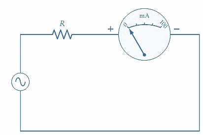
(a) PMMC ammeter connected to alternating current source
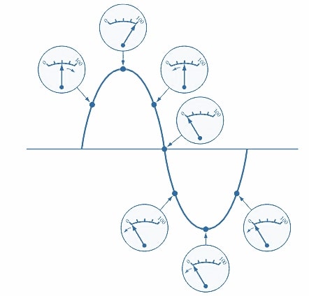
(b) The behavior of PMMC ammeter when measuring a very low-frequency alternating current
Figure 1. A permanent magnet moving coil (PMMC) instrument used directly on sinusoidal alternating current normally indicates zero. The pointer would move up and down the scale on very low-frequency AC. Image used courtesy of Amna Ahmad
Rectification
A rectifier (or semiconductor diode) has two terminals, an anode and a cathode, as illustrated in Figure 2(a). Current can flow through the device in only one direction. When the anode terminal is positive for the cathode, current flows (in the conventional direction) from the anode to the cathode [see Figure 2(b)]. Current will not flow through the rectifier when the cathode is positive for the anode [Figure 2(c)]. When forward-biased (i.e., conducting), there is a small volt drop from the anode to the cathode. This is typically 0.7 V or less, depending on the semiconductor material manufacturing the rectifier. The conventional direction of current flow through the device is indicated by the arrowhead in the circuit symbol, pointing from the anode to the cathode.

(a) The circuit symbol for a rectifier
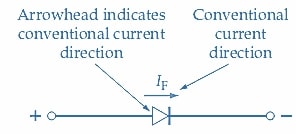
(b) Current flows when the anode is + and the cathode is –

(c) Effectively zero current flows when the cathode is + and the anode is –
Figure 2. The semiconductor rectifier used in AC instruments is a one-way device; it passes current in one direction and blocks current flow in the other direction. Image used courtesy of Amna Ahmad
Figure 3 shows how a rectifier converts alternating current into a series of pulses with the same polarity. In Figure 3(a), a single rectifier is connected in series with a resistor. Only the positive half-cycles of current are passed through the rectifier so that the negative portion of the AC waveform is cut off. The current waveform that passes through the rectifier and the resistor to the output terminals is a continuous series of positive pulses with intervening spaces. This waveform is termed half-wave-rectified.
The circuit shown in Figure 3(b) employs four rectifiers known as a bridge rectifier circuit. When the input waveform is positive [Figure 3(c)], rectifiers D1 and D4 are forward-biased, while D2 and D3 are reverse-biased. So, current flows through D1, resistor R, and D4, as illustrated. Conversely, when the input waveform is negative [Figure 3(d)], D2 and D3 are forward-biased, and D1 and D4 are reverse-biased. Current now flows through D3, resistor R, and D2, and it is seen that the current direction through the resistor is the same as before. The result is that the output waveform [Figure 3(b)] is a continuous series of unidirectional pulses, and the process is termed full-wave rectification.
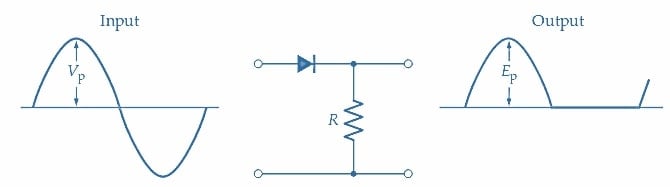
(a) Half-wave rectifier
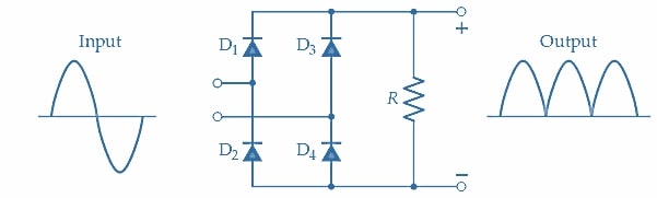
(b) Full-wave bridge rectifier circuit
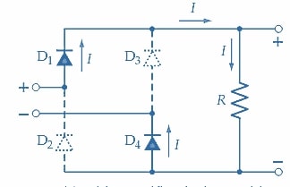
(c) Bridge rectifier during positive half-cycle of input
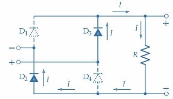
(d) Bridge rectifier during negative half-cycle of input
Figure 3. Half-wave rectifier circuits pass only one-half of each cycle of sine wave input. Full-wave rectifier circuits convert all half-cycles to the same polarity and pass them to the output. Image used courtesy of Amna Ahmad
Rectifier Voltmeter
The circuit shown in Figure 4(a) is that of an AC voltmeter using a PMMC instrument and a full-wave rectifier circuit. As in the case of a DC voltmeter, a multiplier resistance must be included in the circuit to limit the current through the instrument. The actual current that flows through the deflection instrument has the full-wave-rectified waveform shown in Figure 4(b). The deflection of the instrument is proportional to the average level of the current through its coil, so the pointer tends to indicate 0.636 VP. However, the effective value, or rms value, of the alternating waveform is the quantity normally required in any measurement. Because there is a direct relationship between rms and average values, the instrument can be designed to have its scale marked to indicate rms volts. The following example illustrates how this is accomplished.
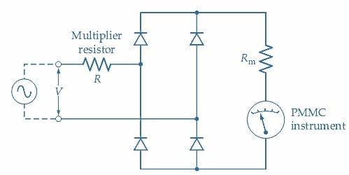
(a) Circuit of an AC voltmeter
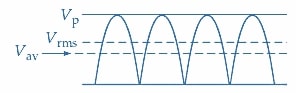
(b) \(V_{P},V_{rms},\,and\,V_{av}\)
Figure 4. AC voltmeter using a full-wave rectifier circuit and a PMMC meter. The meter deflection is proportional to the average of the rectified waveform, but the scale is calibrated to indicate rms values. Image used courtesy of Amna Ahmad
Example
An AC voltmeter to indicate a 100 V rms maximum will be constructed using a deflection instrument with full-scale deflection (FDS) of 500 µA. The coil resistance (Rm) is 1 kΩ, and the rectifiers used each have a 0.7 V forward voltage drop. Using the full-wave rectifier circuit shown in Figure 4(a), determine the required multiplier resistance.
Solution
At FSD, the average current through the deflection instrument is
\[I_{av}=500\mu A\]
For each half-cycle of sinusoidal waveform:
Peak current
\[I_{P}=\frac{\pi}{2}I_{av}=\frac{\pi}{2}\times500\mu A\approx785\mu A\]
Peak voltage
\[V_{P}=1.414V_{rms}=1.414\times100V=141.4V\]
And
\[I_{P}=\frac{V_{P}-(2V_{F})}{R+R_{m}}\]
Giving
\[R=\frac{V_{P}-(2V_{F})}{I_{P}}-R_{m}\]
\[=\frac{141.4V-(2\times0.7V)}{785\mu A}-1k\Omega=177k\Omega\]
It is important to note that rectifier voltmeters designed for sine-wave operation can be used only where pure sine waves are involved. The voltmeter will not correctly indicate the rms voltage if the measured voltage has any other waveform because the 1.414 relationship between rms and peak current levels applies only to pure sine waves. A rotary switch is used to select one of several values of the multiplier resistor for multirange AC voltmeters, exactly as in the case of DC voltmeters.
AC Voltmeter Takeaways
Understanding AC voltmeters that utilize PMMC instruments and the rectification process is important for electrical engineers for several reasons. First, these voltmeters provide accurate measurements of AC voltages, particularly the root mean square (rms) values, which are crucial in electrical engineering for precise representation of effective voltage levels. This accuracy is vital for various design calculations and assessments of system performance. Second, knowledge of AC voltmeters is essential for in-depth circuit analysis and troubleshooting, enabling engineers to identify and diagnose issues such as voltage irregularities or harmonics, facilitating efficient problem-solving. Third, maintaining voltage quality is a priority in power systems and distribution networks, and AC voltmeters play a significant role in monitoring voltage levels to ensure compliance with regulatory standards. Overall, a solid grasp of AC voltmeters and the underlying principles is foundational for electrical engineers, enabling them to ensure accurate measurements in various applications.