Facebook
 Google
 GitHub
 Linkedin
Troubleshooting Common-Mode-EMI in Electric Drive Installations
This article sketches the basic principles and origins of CM currents and uses a case study to show the measurement concepts and counter measures required to conquer CM signals in electric drive installations.
Common-mode (CM) signals frequently occur in variable-frequency drive installations. Especially the high-frequency common-mode voltages introduced by the converter lead to capacitive CM currents flowing from stator windings to ground through different paths of the machine. This not only stresses the different insulation layers but also severely damages the bearings of the motor, leading to a significant reduction in the machine’s lifetime.
Common Mode Noise
Based on the individual line voltages of the electric drive output, the common-mode component of an electric drive output can be calculated by which is identical to the zero sequence component when using symmetric components [1] [2].
\(V_{CM}=\frac{1}{3}\left(V_{a}+V_{b}+V_{c}\right)\) , (1)
While low frequency CM harmonics can be controlled by adapted modulation schemes, the high-frequency components driving the CM current flowing through the machine highly depend on the different components themselves, but also their mutual interaction and different installation parameters. Minimizing high frequency CM noise therefore often requires additionally optimize the system after installation.
Even though there is no explicit CM path in most applications, parasitic capacitances, as shown in red in Figure 3, allow for common-mode currents if CM voltages are present.
In real setups, mostly neither the stray capacitances nor the line or load impedances are identical. Thus, the common-mode voltage will lead to a current distribution with IL1 ≠ IL2 ≠ IL3, resulting in different voltage drops across the nodes of the load which is measurable as differential-mode disturbances. This phenomenon is hence called common-mode differential-mode (CMDM) conversion. Analogously, it is also possible for DM disturbances to be converted into CM signals (DMCM conversion)
Note, that also EMI-filters, which are usually inserted between line and converter or line and load, can lead to CMDM or DMCM conversion [3] [4].
Problems with Common Mode Noise in Power Drive Systems Besides the need to meet the EMC standards for power drive systems [5], CM signals may cause severe damages to the machine. As can be seen in Figure 1, a certain portion of the CM currents flow from the stator windings towards the rotor via parasitic capacitances. While one part (blue) of the CM current directly flows to ground via the capacitance between stator winding and stator itself, another part flows to the rotor via the stator-winding to rotor capacitance. From here, the current will either flow to ground via the stator-rotor capacitance (green) or take the path through the bearings of the machine (yellow).

Figure 1. Different current paths for high-frequency CM currents induced to the machine by the converter. Image used courtesy of Bodo's Power Systems magazine.
Due to the lubricant insulation film building up at high rotor speed (n>100/min), the bearing impedance is mainly capacitive. However, random contacts or dielectric breakdowns lead to sudden discharge effects of these capacities via the spheres inside the bearings. This results in high currents flowing through the contact point between the bearing ball and the races, causing fluting, scoring, and cracks or fractures. These damages accumulate over time, leading to bearing failure eventually and reducing the lifetime of the machine drastically, involving high costs due to downtimes [6].

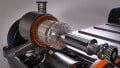
Figure 2. Measurement of CM current with three different Rogowski coils from PEM UK [8] - left: PEM CWT Ultra mini, middle: PEM CWT miniHF, right: PEM custom made (2 windings). Image used courtesy of Bodo's Power Systems magazine.
Measuring CM signals
The CM current can be easily and accurately measured on site using handheld oscilloscopes like the R&S RTH1004 in combination with high-bandwidth Rogowski coils [7]. Here, the CM current can directly be measured by closing the Rogowski coil around all three phases, as shown in Figure 2. We note that it is crucially important for a valid measurement to exclude the cable screen from the measurement, as shielding currents will otherwise influence the measurement. As schematically shown in Figure 3, this can usually simply be realized directly at the converter output ① or at the machine input ②.

Figure 3. Measurement of CM current using Rogowski coils (blue) either at the converter output ① or at the machine input ②. Image used courtesy of Bodo's Power Systems magazine.
The high-frequency CM current signals usually consist of pulse patterns. It is important to carefully adjust the trigger to the peakvalue. Otherwise, the oscilloscope might display a maximum value lower than the actual one. This is one of the most frequent reasons for underestimations of CM currents.
Counter Measures
An efficient way to reduce the CM currents flowing into the machine is to increase the common-mode impedance. This can efficiently be achieved with current compensated chokes. Here, all three phases are fed through high permeability ring cores. Since the differential currents are canceling out, the choke introduces an impedance for the CM current only.

Figure 4. Four high-permeability ring cores are connected in series as current compensated chokes with 2 windings in total. Image used courtesy of Bodo's Power Systems magazine.
Depending on the application, a certain ring-core geometry, material, and the number of windings are to be used to sufficiently increase the CM impedance of the choke. For the right choice of the core, tables [9] [10] or online simulation tools [11] can be used. In Figure 4, four high-permeability ring cores from MAGNETEC were used as current compensated chokes with two windings each. The effect of these measures is displayed in time domain in Figure 5. As can be seen, the peak-value is reduced from 13.77 A to 3.15 A, which is more than a factor of four.
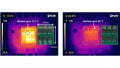
Another useful way to visualize the effect of the applied counter measures is the FFT function of the oscilloscope, as it directly allows to investigate of the effect of a specific measure on the frequency range of interest. Figure 6 shows the effect of the four chokes displayed in the frequency domain, using the oscilloscopes FFTfunction.


Figure 5. Typical CM-current pulse pattern without counter measures (upper screen) and after the injection of current chokes (lower screen). Image used courtesy of Bodo's Power Systems magazine.


Figure 6. Visualization of the frequency of the CM current using the FFT-function of the oscilloscope. The spectrum before the insertion of the chokes is shown on the left, the spectrum after the insertion is shown on the right side. Image used courtesy of Bodo's Power Systems magazine.
The measurement of the frequency spectrum becomes especially important since every EMI-filter including current compensated chokes introduces new energy-storage components in form of capacitances or inductances, which can cause additional oscillations, resonances, or even instabilities. Therefore, the effect of filter elements on the system behavior should thoroughly be measured for all operation points.
Summary
Common-mode (CM) currents are one of the main causes for bearing failures and can thus significantly reduce the lifetime of electric drives. Therefore, CM interferences need to be thoroughly investigated after installation on site. Here, handheld oscilloscopes in combination with Rogowski probes are powerful tools to easily determine these CM currents and to measure the effect of counter measures. In this article, the measurement of CM quantities is shown in addition to the insertion of current compensated chokes (CCC) as an affective counter measure. The measurements show that the usage of four magnetic ring-cores acting as CCCs, the peak current is reduced by more than a factor of four.
This article originally appeared in Bodo’s Power Systems magazine.