 Facebook
 Google
 GitHub
 Linkedin
Troubleshooting a Programmable Logic Controller
This article covers commonly used methods for troubleshooting a programmable logic controller (PLC) that is experiencing an error.
Usually, the source of most problems in a logic controller can be narrowed down to malfunctions in one of the following areas:
1. Processor module
2. Inputs
3. Outputs
4. Ladder Logic program
In addition to checking the power voltage using a multimeter (assuming that you know the required IO), you must check each of these areas for specific faults, as discussed below.
Processor Module
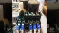
The processor performs error checks and sends status information to indicators typically located on the front of the processor module. The CPU contains three LED lights: RUN, FLT, and BATT, as shown in Figure 1. The first step is to check the lights.
The RUN light should be green, indicating that the PLC is in RUN mode.
If the BATT light is red, the battery needs to be replaced. The EPROM inside the PLC will hold the PLC program just long enough to allow you to replace the battery. It is essential that you replace the battery as soon as the PLC detects a low battery level since the PLC program will be lost in the event of battery failure.
Note that the batteries are used to back up the RAM and to provide power to the clock. Usually, the battery is located on the side or on the front of the PLC, and it should be accessible without removing or moving the PLC main unit from the rack/socket. Batteries typically need to be replaced every five years.

Figure 1. Central Processing Unit (CPU).
Input Malfunctions
The first step in troubleshooting input malfunctions is to check your inputs for proper wiring, identifying your PLC IO from the provided schematics.
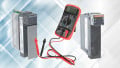
Then, typically, the problem source can be narrowed down by comparing the actual status of the suspect I/O with the controller status indicators. Refer to Figure 2.
Make sure to check the Input LED for its ON/OFF status.

Figure 2. Input status LED indicator.
Output Malfunctions
As with input malfunctions, the first step in troubleshooting an output malfunction is to check the outputs for proper wiring, identifying the PLC IO from the provided schematics.
If the output circuit LED is on and the output device is OFF, several things could be the cause:
- Incompatible devices: Check for PNP/NPN output specification.
- Wrong output circuit wiring: Check output module wiring.
- Low or NO voltage across the load: Check for short-circuit or damaged wires.
Aside from the logic indicator, some output modules have a blown fuse indicator, a power indicator, or both. Electronic protection is also used to protect the modules from "short circuit" and "overload current conditions" problems. See Figure 3 for an example.

Figure 3. Output status LED indicator.
PLC Program Error
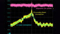
The final step involves running an error check to verify the PLC program. By selecting "edit" and then "verify project," the program will be checked for errors. See Figure 4. Specifically, follow these steps:
- Start program troubleshooting by identifying the outputs that operate properly and the outputs that do not.
- Identify common logic errors.
- Use Force On/Force Off to turn specific bits on/off for testing purposes.

Figure 4. PLC Program Error.
Conclusion
When performing checks in each of the four areas covered here, keep in mind the following:
• The majority of faults in PLC systems occur in the field wiring and devices.
• Problems are most likely to occur in the wiring between the field devices and the I/O module terminals.
• The sensors and actuators that are connected to the process's I/O can also fail.
• If an instruction does not appear to be working correctly, it could be due to an addressing conflict caused by the use of the same address for two or more coil instructions in the very same program.
• Even if the monitored rung is true, the PLC will turn off the output if a rung farther down the ladder diagram is false.
Featured Image used courtesy of Process Solutions, Inc.


Great overview! This step-by-step breakdown reinforces how critical it is to isolate faults by category—especially when dealing with field wiring issues, which are often the root cause. At INS3, we’re seeing more manufacturers integrate smart diagnostics and real-time PLC monitoring into their analytics stack. Curious—has anyone tried combining these troubleshooting practices with predictive maintenance algorithms? The synergy can significantly reduce downtime.