Facebook
 Google
 GitHub
 Linkedin
Trench Schottky Rectifiers Reduce Trade-Offs and Deliver Increased Performance
Schottky diodes feature a low forward voltage drop and high switching speed suiting them to a wide variety of applications, such as a boost diode in power conversion circuits. However, there have been trade-offs concerning forward voltage drop, the leakage current, and the reverse blocking voltage.
Today, Trench Schottkys address this challenge and provide greater capabilities than their original planar counterparts, reducing switching losses, and delivering a wider SOA and lower Qrr.
Schottky trade-offs
The ideal rectifier would have a low forward voltage drop, a high reverse blocking voltage, zero leakage current, and low parasitic capacitance, facilitating a high switching speed. When considering the forward voltage drop there are two main elements: the voltage drop across the junction – PN junction in case of PN rectifiers and metal-semiconductor junction in case of Schottky rectifiers; and the voltage drop across the drift region. While the forward voltage drop across a PN junction is intrinsically determined by the built-in voltage and hence, mainly by the specified semiconductor material, the forward voltage drop across the metal-semiconductor interface in a Schottky barrier rectifier can be modified by the choice of the Schottky metal, with the Schottky barrier being the result of the difference between the metal work (MW) function and the electron affinity of the semiconductor.
By using Schottky metals with a low MW function, the voltage drop across the metal semiconductor interface can be minimized. However, there is a trade-off between the forward voltage drop across the junction and the leakage current of the Schottky rectifier, as the level of the leakage current is also determined by the Schottky barrier and the electrical field across the metal-semiconductor interface. Also, the advantage of the low voltage drop across the junction can disappear when the thickness of the drift region is increased to achieve a high reverse blocking voltage. This is why the reverse blocking voltage of Schottky rectifiers is traditionally limited to less than 200 V.
Trench technology
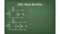
The challenge, therefore, is how to preserve the low voltage drop across the metal semiconductor interface given the demand for a low leakage current and a high reverse blocking voltage? Here, Trench rectifiers prove very useful. The concept behind the Trench Schottky rectifier is termed ‘RESURF’ (reduced surface field). The RESURF effect is illustrated in Figure 1. In a planar Schottky rectifier the equipotential lines are concentrated close the top electrode, resulting in a high electrical field near the surface. This results in a strong increase of the leakage current with increasing reverse voltage, and an early breakdown when the critical electrical field is exceeded near the surface.

Figure 1. Equipotential lines in a planar Schottky rectifier (left) and in a Trench Schottky rectifier (right) in reverse direction. Image used courtesy of Bodo's Power Systems
By etching trenches into the silicon and filling them with poly-silicon – electrically separated from the drift region by a thin dielectric – the trenches act like a field plate in the semiconductor, depleting the drift region in reverse direction and resulting in a flattened electrical field profile along the drift region. Therefore, the trench structure achieves a lower leakage current by reducing the electrical field near the surface and producing a higher breakdown voltage compared to a planar device with the same epitaxial structure.
At Nexperia, a portfolio of Trench Schottky rectifiers has been developed and launched with a voltage range of 45-100 V (PMEG*T family). These devices achieve a well-balanced trade-off between the forward voltage drop (Vf) and the leakage current (IR). As an example, the Vf / IR trade-off for 60 V products is shown in Figure 2. In this figure, the leakage current at maximum reverse voltage is plotted against the forward voltage drop at maximum forward current at 125°C. For comparison, Trench and planar Schottky rectifiers from two other manufacturers are shown in this graph. For a given forward voltage drop, the Nexperia device exhibits the lowest leakage current.

Figure 2. Vf / IR trade-off at maximum reverse voltage and maximum forward current at 125°C. Image used courtesy of Bodo's Power Systems
Wide safe operating area (SOA)
The lower leakage current of Trench Schottky rectifiers compared to their equivalent planar counterparts with comparable forward voltage drop shows the Trench devices have a wider safe operating area (SOA). SOA plots the maximum reverse voltage that can be applied against the junction temperature. As well as the intrinsic SOA advantages offered by Trench rectifiers compared to planar Schottkys, Nexperia Trench products have additionally been designed with special attention to creating a wide SOA. Figure 3 shows the SOA at a thermal system resistance (Rth(j-a)) of 90 K/W of a Trench Schottky (PMEG100T080ELPE - orange line) versus a similarly-rated Trench Schottky device from another supplier (blue). At 125°C junction temperature the maximum allowable reverse voltage of the Nexperia Trench device is almost 40 V higher than the competitor’s Trench product.

Figure 3. Comparison of safe operating area of Nexperia’s PMEG100T080ELPE Trench Schottky versus a Trench Schottky part from a competitor. Image used courtesy of Bodo's Power Systems

Figure 4. Cross section and equivalent circuit diagram of a Trench Schottky rectifier, highlighting the circuit elements. Image used courtesy of Bodo's Power Systems
Therefore, in applications where higher ambient temperatures will be experienced such as automotive, Trench Schottky rectifiers are a suitable choice since they are more robust against thermal runaway (the instability that occurs when the increase of the dissipated power caused by the leakage current of the rectifier is faster than the heat dissipation through the thermal resistance of the system) shown in Figure 4. Besides the usual parasitic capacitance of the Schottky diode, CDIODE, there is a second parasitic capacitance caused by the electrode and the thin dielectric in the Trench structures, CTRENCH. This means that per unit area the total parasitic capacitance of a Trench Schottky rectifier is higher than its planar counterpart.
However, CTRENCH does not affect the diode switching characteristics or EMI; in fact, Trench rectifiers have less stored charge, Qrr, and show an excellent switching performance when compared to planar Schottkys despite this overall larger parasitic capacitance.

| Qrr (T=25°C) | Qrr (T=85°C) | IRM (T=25°C) | IRM (T=25°C) | |
| Trench Schottky | 8.6 nC | 8.5 nC | 2.8 A | 2.7 A |
| Planar Schottky | 26.3 nC | 33.5 nC | 5.2 A | 5.2 A |
Figure 5. Reverse recovery behaviour of Trench and planar Schottkys. Image used courtesy of Bodo's Power Systems
Reverse Recovery Behaviour and QRR
The switching behaviour of a device is characterized by reverse recovery measurements. Such measurements are carried out by biasing the rectifier in a forward direction, then switching the device into a reverse condition. Due to the stored charge in the device (represented by the parasitic capacitance, CDiode, in the equivalent circuit, Figure 4) which must be first removed before the diode blocks, a so-called reverse recovery current of the rectifier occurs. The ramp reverse recovery measurement for a Trench Schottky rectifier and its planar counterpart with comparable die size and package is shown in Figure 5.

Figure 6. Trench Schottky rectifiers deliver significant converter efficiency benefits, especially at higher frequencies where their switching losses are less than planar devices. Image used courtesy of Bodo's Power Systems
In this measurement, the current has been ramped down with a di/ dit rate of 1 A/ns. The area under the zero line represents the Qrr of the rectifier. The blue line shows the lower Qrr of the Trench device.
The graph also shows the lower reverse recovery current and the shorter reverse recovery time of the Trench rectifier compared to its planar counterpart (despite its higher parasitic capacitance, as discussed earlier). The temperature stability of Qrr for Trench rectifiers is particularly notable, since applications very rarely operate at 25°C. As shown in Figure 5, the Qrr of the Trench rectifier barely changes at an elevated 85°C ambient temperature while the Qrr of a planar Schottky increases significantly.


Figure 7. Impact on electromagnetic emission: radiated emission (left); conducted emission (right). A 48 V /12 V buck converter is used as the test vehicle; 3 A CFP3 rectifiers. Image used courtesy of Bodo's Power Systems
The impact of the lower Qrr of the Trench Schottky on the efficiency of a 48V/12V switch-mode converter is shown in Figure 6. The low Qrr of the Trench Schottky rectifiers results in significant converter efficiency gains, especially at high frequency where switching losses are greater.
Any ringing that occurs in the Trench rectifier during switching does not impact electromagnetic emission levels, as confirmed by conducted and radiated emission measurements shown in Figure 7.
Conclusion
In summary, Trench rectifiers are a suitable choice if a better tradeoff between forward voltage drop and the leakage current is required. Trench rectifiers should also be selected in high power density applications where the ambient temperature is elevated since they are more robust against thermal runaway effects. For applications with switching speeds above 100 kHz, the reduced switching losses of the Trench devices are particularly significant. Readers can watch the Trench Schottky technology in action presentation and speak to experts at Nexperia’s online Power Live Event: 21 – 23 September www.nexperia.com/power-live
This article originally appeared in Bodo’s Power Systems magazine.
Related Content