Transformer Inspection and Testing
Installing a transformer is more than just connecting the wires, according to the wiring diagram. The first part of the installation process includes an initial inspection and testing of the transformer when it is received from the factory or warehouse. After a successful inspection, the installation can begin.
When a transformer arrives at a factory or job site, there are several things that should be inspected before accepting the shipment. For larger power transformers, there are some electrical tests that should be performed to verify that the unit was manufactured correctly and is in satisfactory condition. It is best to inspect and test a transformer before installation and before it is energized for the first time to ensure that it is in good working order.
A complete drawing of the coils and the regulator is found on the transformer nameplate. The nameplate gives the installer all of the data relating to the transformer, including the rating, impedance, primary and secondary voltage, the phasing, the allowable temperature rise, oil type (if used), weight, and connection diagrams. Also included are the name of the manufacturer, the model number, and the serial number.
Inspection
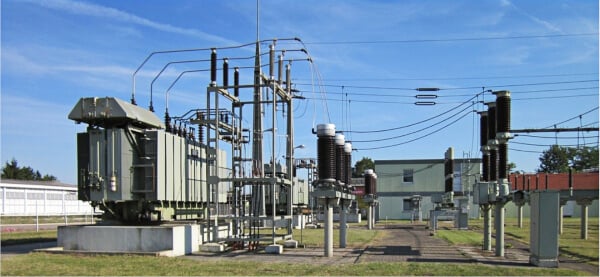
The first thing to do is to inspect for any damage that could have occurred during shipping. The bushings and the insulators should be inspected for cracks and chips in the porcelain. See Figure 1. The exterior finish should be inspected. If the paint has been worn or scraped off, it must be repaired. A unit that sits outside or in a corrosive environment will corrode, and leaks may develop. The cooling fins, if present, should be inspected for dents that may affect the ability of the cooling system to operate.

Figure 1. When a new transformer arrives, the bushings and exterior finish must be inspected before installation.
Insulation Resistance
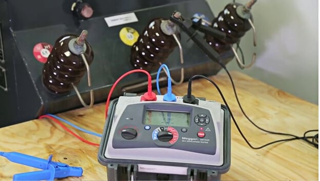
A relatively common problem with transformers is insulation failure between the coils. An insulation resistance test is a test performed to measure the leakage current through the coil insulation. When the leakage current is too high, the insulation can fail and short out the coil. An insulation resistance test should be conducted with a hipot tester or a megohmmeter. See Figure 2. Megger® is a company that manufactures megohmmeters and other test tools. The company name has become a common name for a megohmmeter.

Figure 2. The transformer insulation should be tested before the transformer is installed.
There are several conditions that should be met for best results from insulation resistance testing. The transformer should not be in service and should not be connected to any circuits, switches, capacitors, etc. The temperature should be above the dew point of the ambient air to prevent a moisture coating from forming on the insulation surface.
The test voltage should be at the correct level. Too much voltage can overstress or damage insulation. Each winding should be tested individually with all the other windings grounded. The transformer manual should give the allowable voltage and type of test required. A transformer rated at 600 V or less can typically be tested with a 500 V or 1000 V megohmmeter to look for any leakage to the ground or between the primary and secondary.
Capacitors are sometimes used for power factor correction, and they must be discharged or disconnected before the transformer is tested. The temperature must be considered. The tests should be conducted at a temperature of 68°F (20°C).
Winding Resistance
A winding resistance test is a test performed to measure the electrical resistance of the transformer windings. If the resistance increases, extra heating of the wire making up the windings occurs. This can cause the coil to burn out if the temperature gets hot enough to soften or melt the wire.
A precision ohmmeter is used for this test. All windings must be tested, so a load tap changer must be cycled through all its possible positions. For a very large transformer, such as a 20 MVA unit in a substation, this testing can take several hours.
Turns Ratio
A turns ratio test between the primary winding, and secondary winding can be run to verify that all the windings are wired and operating correctly. Again, all windings should be tested, so a load tap changer must be cycled through all its possible positions since these devices effectively change the transformer turns ratio. Kits and test tools are available from test equipment suppliers to simplify this testing.


ITS VERY NICE & CLEAR LEARNING FOR ELECTRICAL ENGINEER.