Facebook
 Google
 GitHub
 Linkedin
Three-Phase Transformers: Applications and Connection Configuration
Transformer types can vary from small instruments to large power distribution systems. Three-phase systems require transformers that employ the same Wye and Delta arrangements common to industrial motors.
Transformers are critical electrical devices for power transmission, taking in power at one voltage and dispatching it out at another voltage. It can increase or decrease the voltage or current in an AC circuit and isolate circuits.
Transformers work on the fundamental principle of electromagnetic induction to transform energy from one circuit to another. They are commonly associated with power systems and low-power applications, including electronic circuits.
Transformer Functions and Applications
The types and uses of transformers vary widely and can be categorized on their application, construction type, and size.
Generally, the key function of a transformer is to change the voltage level of an alternating current (AC) and step up the voltage to transmit over a long distance or step down the voltage for domestic and industrial consumers.
They range in size from minute low-voltage and instrument transformers to power transformers. In large hydropower plants, the electric power is generated at a voltage level ranging from 11 kV to 25 kV. Subsequently, the transformer steps up the voltage to 220 kV or 500 kV to dispatch electricity to distant areas via high-voltage transmission lines and then further distributed for industrial and domestic utilization after stepping down.
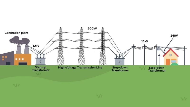
Figure 1. The transformer steps up the voltage to 220 kV or 500 kV to dispatch electricity (created in Canva)
A simple transformer consists of one winding connected to an AC generator wound around a laminated iron core, and a second separate winding around the same core is connected to a load.
As the power flows from the generator to the load, the winding connected to the generator is the primary winding. Another winding connected to the load is the secondary winding.
Step-Up and Step-Down Transformers
If the voltage induced in the secondary winding is higher than the source voltage, the transformer is known as a step-up transformer, and the primary winding would then also be known as the low-voltage winding and the secondary as the high-voltage winding. If the voltage induced in the secondary winding is lower than the source voltage, the transformer is a step-down transformer. The primary is the high-voltage winding, and the secondary is the low-voltage winding.
The transformer can step up to some higher voltage for transmission, and an identical transformer can step down the voltage at the other end of the line. Therefore, the terms step-up, step-down, primary winding, and secondary winding are only used when the circuit is considered—the transformer itself will not necessarily be restricted to one function.
The voltage ratio in two coils depends on the transformer’s design characteristics. The terms high-voltage and low-voltage winding refer to definite coils regardless of the circuit to which the transformer is connected. The turn ratio is the ratio of the number of turns in the primary winding to the number of turns in the secondary winding.
Transformer Types
In considering their construction, transformers could be grouped into two classes: power and distribution transformers and instrument transformers.
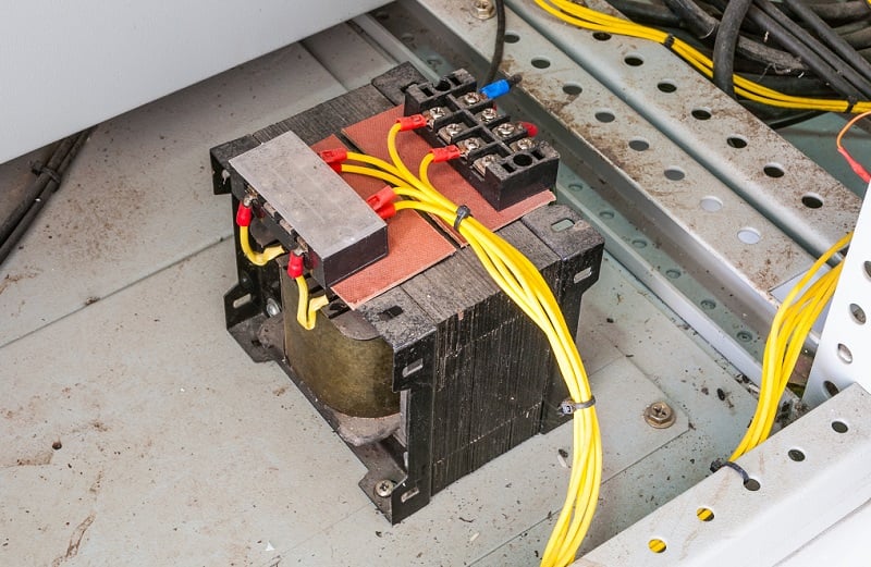
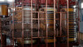
Figure 2. Transformers can exist inside the industrial control system to step the voltage down to device-applicable levels. Image used courtesy of Adobe Stock
A power transformer is rated above 500 kVA and used to transmit power. A distribution transformer is rated at 500 kVA or less and steps down the voltage for distribution at standard service voltage.
From the generating system to the sub-station, power transformers are used in the transmission network and can step up and down the voltage. From the substation onward, the distribution transformers are installed in the distribution network, such as in industrial and residential areas, and different loads are directly connected.
Although instrument transformers function on the same basic principle as power transformers, their purpose and construction can differ. They are used to reduce electrical quantities, current, and voltage of power circuits to values that can be read by instruments or utilized to operate relays.
As for the arrangement of the core and coils, transformers can be divided into core-type and shell-type, and both types of transformers are manufactured and give satisfactory service. Three-phase transformers can be built either core-type or shell-type, and the advantage of a 3-phase transformer over three single-phase transformers is that it takes less material, labor, and space. The main disadvantage is that if one coil fails, the entire transformer must be removed and dismantled for repair. In contrast, if one coil of a bank of three 1-phase transformers fails, the remaining two can still carry the reduced load.
Transformer Windings
Three-phase transformers are used to transform 3-phase voltage in a 3-phase electrical system, and windings can be connected in several combinations. For example, the primary may be connected to Delta, and the secondary may be connected to Wye or vice versa.
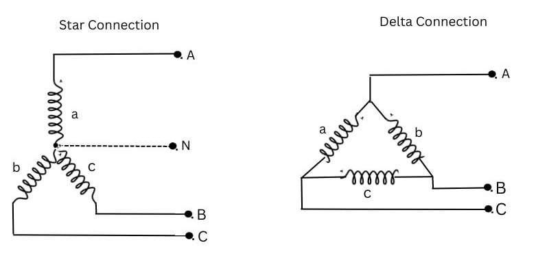
Figure 3. Wye and Delta connection configuration (created in Canva)
Delta-Delta Transformer Connection
In this scheme, the primary and secondary windings of the transformer are connected in the Delta-Delta configuration, which is usually used in the generating system or at the receiving station. In this type of connection, we have only three phases and no neutral, so it is used where there is no need for a neutral, such as in transmission lines. The transmission system is called a 3-phase 3-wire system.
Delta-Wye Connection
The step-down transformers are installed at the distribution level to step down the voltage level used for electricity distribution and configured in the Delta-Star connection. We use a start connection because we need neutral at the distribution level. It is also called a 3-phase 4-wire system. In the Delta, we have three phases on the primary side, and on the secondary side, we have four wires containing 3-phase and one neutral wire. In a Delta connection, the line current is \(\sqrt{3}\) times the phase current, and the line voltage equals the phase voltage.
Wye-Wye Connection
In the Wye-Wye connection, the primary and secondary windings are connected in the Wye configuration. There are two points to remember in a Star-Star connection: the line current and phase current are equal and in phase, but the line voltage is \(\sqrt{3}\) times the phase voltage.
Wye-Delta Connection
In the Star-Delta connection, the primary winding is connected to the Star, while the secondary winding is connected to the Delta. On the transformer’s primary side, connected in the start configuration, the line voltage equals the \(\sqrt{3}\) times the primary phase voltage, and the primary line current is the same as the phase current. Likewise, the secondary winding of the transformer is connected in a delta configuration. The line voltage equals the phase voltage, and the line current is \(\sqrt{3}\) times the phase current. The advantage of having a Star configuration at the primary side is that neutral is available, which can be grounded to avoid distortion. These types of transformers can handle large unbalanced loads.
Delta-Wye connection is common for high-voltage and low-voltage applications. The Wye-Wye connection is used for high voltage and low current rating transformers (KVA). The Delta-Delta connection is used for low voltage and high current rating transformers.
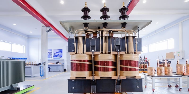
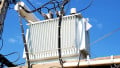
Figure 4. 3-phase transformers for power delivery use large coils to step voltage up and down. Image used courtesy of Adobe Stock
Failure Types in Power Delivery Transformers
The transformer is one of the transmission and distribution network’s most costly and integral components. Therefore, regular maintenance schedules and tests are prerequisites. Like all electrical devices, different faults appeared in the transformer for multiple reasons. They could seriously impact the power system, such as power supply interruption in large areas and risk of fire, etc.
Multiple mechanical and electrical factors cause faults in the transformer’s internal and external parts. Let’s discuss the most common faults that happen in the transformer.
Open Circuit and Short Circuit
The open circuit and short circuit tests are performed without loading a transformer and are carried out to determine its efficiency and regulation. The open circuit test is also called the no-load test, and the short circuit test is called the on-load test.
The open-circuit test is performed on the low-voltage side of the transformer to find the no-load current and losses of the transformer, i.e., core and iron losses. As the transformer is on no-load, the secondary winding of the transformer is kept open, and a very small ‘no-load’ current flows through the primary winding. Therefore, the power loss in the transformer at no load is due to copper loss, which occurs only on the primary winding because the secondary winding is open. The open circuit in the transformer can cause abnormal heating inside the transformer, which is dangerous, and it is pertinent to mention here that when the open-circuit fault occurs, it is important to disconnect and isolate the transformer from the system.
In the short-circuit test, the secondary winding of the transformer is short-circuited, and the rated voltage is supplied to the primary winding. The test aims to determine the impedance and losses of a transformer when its secondary winding is short-circuited, and parameter information is used to determine the transformer’s efficiency and voltage regulation. The ammeter measures the short-circuit current, and the voltmeter measures the voltage across the primary winding.
Cooling System Failure
Most power and distribution transformers are oil-immersed with different types of cooling depending on their size. As the transformer rating increases, the surface area must be increased by adding external cooling pipes, fans, radiators, and heat exchangers. The failure of the cooling system will heat the transformer, which causes the gas pressure to be built inside the transformer.
If an adequate supply of cool water is available, oil-immersed water-cooled transformers are satisfactory. In this method, cooling water is circulated through the cooling coils located inside the transformer. The main disadvantage to this type is the danger of leaks in the coils, as the water would leak out of the coils and contaminate the oil.

Figure 5. Large insulators can indicate the presence of the high-voltage side of a transformer (three wires on one side and four wires on the other indicate a Wye-Delta configuration). Image used courtesy of Adobe Stock
Transformer Efficiency
Efficiency is the ratio of output power to input power, denoted by the symbol “η”. In an ideal transformer, all the input power is converted to output power; therefore, the efficiency is 100%, but in practical applications, some losses reduce the efficiency of the transformer. The losses in a transformer can be divided into two groups:
- I2R losses in primary and secondary windings due to wire resistance
- Core losses due to hysteresis and eddy currents
Hence, If Pc = total core loss, then the total loss in a transformer is:
$$P_c+{I^2}_1 R_1+{I^2}_2 R_2$$
and
$$Efficiency = \eta$$
$$\eta = {P_{output} \over P_{input}}$$
$$\eta = {P_{output} \over P_{output}+losses}$$
3-Phase Transformers
An electrical transformer is a costly and static device that transfers electrical energy from one circuit to another using the principle of electromagnetic induction. The types and uses of transformers vary depending on their applications, such as power and distribution transformers in the power generation transmission and distribution sectors and instrument transformers for metering purposes.