Winding Connections and Applications of Buck-Boost Transformers
This article will teach you about buck-boost transformers, winding connections, and their applications. The primary focus is on boosting (raising) or bucking (lowering) voltages for various applications, such as matching supply voltages to foreign motors and overcoming voltage drops, with detailed explanations and examples provided.
Most autotransformer applications involve boosting (raising) or bucking (lowering) voltages. For example, they can match standard U.S. supply voltages to foreign motors and equipment that operate at nonstandard voltages, change a 240-V supply to 208-V for a motor, or overcome voltage drop. These boost/buck applications use a standard two- or four-winding isolating transformer, but the H and X windings are connected, so they are no longer isolated.

Image used courtesy of Adobe Stock
Boost Transformer Winding Connections
In Figure 1, a 120 V – 24 V rated transformer is configured as a boost transformer. The power is supplied to the H winding, and the load is connected to the H and X windings in series. The supply voltage is applied to the smaller number of turns, and the secondary voltage is across the higher number of turns. The rule of transformer winding turns and voltage still holds; the voltage is proportional to the turns of the windings—only now, the primary and secondary voltage windings are not isolated.

Figure 1. A boost transformer connection shows how the secondary winding voltage adds to the primary winding voltage. Image used courtesy of Ahmed Sheikh
A boost transformer has the supply voltage applied to the smaller number of turns, and the secondary voltage is across the larger number of turns. With the opposite polarity X and H leads connected, the voltage induced in the X winding adds to the voltage of the H winding, thus boosting it. Because the number of turns is proportional to the voltage of a transformer, the number of turns in each winding is the same as the voltage of the winding. The secondary voltage must be:
\[\frac{120\,Turns(Pri)}{120\,Turns+24\,Turns(Sec)}=\frac{120V}{V_{s}}144V\]
The transformer will boost the supply voltage, and the secondary voltage is now 120 V + 24 V = 144 V.
Tech Tip
The boost transformer connection applies power to some of the turns of the two windings in series and connects the load to all the turns of the windings. The output voltage equals the input voltage plus the voltage of the X winding.
Buck Transformer Winding Connections
What would happen if the two windings were left connected the same way, but the supply voltage was now connected to the H and X windings in series, and the load was connected across only the H winding, as shown in Figure 2? A buck transformer has the supply voltage applied to the larger number of turns, and the secondary voltage is induced in the smaller number of turns. The number of turns on the primary winding—the H and X windings in series—is more than the number of turns on the secondary winding: the H winding. Therefore, the voltage induced in the secondary winding will be less. The secondary voltage must be:
\[\frac{120\,Turns+24\,Turns(Pri)}{120\,Turns(Sec)}=\frac{120V}{V_{s}}100V\]
The transformer will buck the supply voltage; the secondary voltage is 120 V – 20 V = 100 V.

Figure 2. Buck transformer connection shows how the secondary winding voltage subtracts from the primary winding voltage. Image used courtesy of Ahmed Sheikh
Let’s look at an example. Because of voltage drop, the voltage at a 120-V motor is only 110 V. What is the voltage rating of a boost transformer that will raise the voltage to at least 120 V?
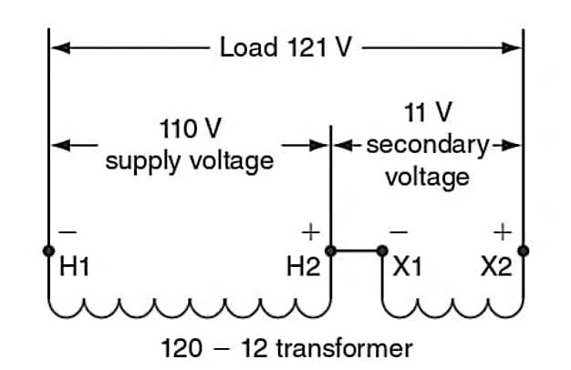
Because the voltage required is 10 V greater than the actual voltage at the motor, the boost transformer X winding must add at least 10 V to the primary winding. The nearest standard boost transformer rating is 120 – 12. What will the output voltage of this transformer be if we connect the transformer, as shown in Figure 3?
Based on the voltage rating of the transformer, the turns ratio must be 120 turns to 12 turns; with the H and X windings in series, the total number of turns is 120 + 12 = 132 turns. Because this is a boost transformer, the secondary is the larger number of turns; the primary voltage of 110 V will result in a secondary voltage of:
\[\frac{120\,Turns(Pri)}{132\,Turns(Sec)}=\frac{110V}{V_{s}}121V\]

Figure 3. A 120 – 12 transformer is connected as a boost transformer, showing input and output voltages. Image used courtesy of Ahmed Sheikh
Tech Tip
The buck transformer connection supplies power to all the turns of the two windings in series and connects the load to some of the turns of the windings. The output voltage equals the input voltage minus the voltage of the X winding.
If the 110 V in the example were applied to the H and X windings in series and the secondary winding was the H winding, as shown in Figure 4, we would have a buck transformer. The ratio of turns would result in a secondary voltage of:
\[\frac{132\,Turns(Pri)}{120\,Turns(Sec)}=\frac{110V}{V_{s}}100V\]

Figure 4. A 120 – 12 transformer is connected as a buck transformer, showing input and output voltages. Image used courtesy of Ahmed Sheikh
Dual Primary and Secondary Windings
Most buck-boost transformers have dual primary and secondary windings; thus, one transformer can be used for multiple applications. When connecting for different boost or buck voltage values, the individual X windings are connected in series for a high voltage and in parallel for a lower voltage. For example, a 120 X 240 – 16 X 32 transformer can boost a voltage from 240 V to 256 V if the X windings are connected in parallel and from 240 V to 272 V if the X windings are connected in series. Figure 5 shows the connections. The buck connection would produce secondary voltages proportionally less than the supply voltage.

Figure 5. Boost connections with windings in parallel and in series. Image used courtesy of Ahmed Sheikh
Buck-Boost Transformer Takeaways
Learning about buck-boost transformers and their winding connections is crucial for engineers in the electrical field. These transformers are vital in adjusting voltages to meet specific requirements, ensuring compatibility between power sources and equipment. Applying boost and buck connections enables efficient utilization of electrical systems, addressing challenges like voltage drops and mismatched standards. Proficiency in these concepts is essential for engineers, as it empowers them to optimize electrical configurations, enhance equipment performance, and maintain reliable power supply in diverse scenarios.


