Facebook
 Google
 GitHub
 Linkedin
Thermal Management of Semiconductors
This article introduces EPCOS' NTC and PTC sensors with different characteristics for thermal management of a wide variety of semiconductor application.
Power semiconductors are the workhorses of the electronics world. Their thermal management is crucial to the operational reliability and service life of the components. For this purpose TDK offers a wide range of EPCOS NTC and PTC thermistors that enable reliable temperature monitoring.
Power semiconductors generate thermal losses, ranging from a just a few watts to several kilowatts, which must be dissipated. Due to their need for thermal management, the enclosures of power semiconductors are designed in such a way that they can be mounted on heatsinks in order to dissipate the heat more efficiently. The conductive capability of heatsinks is measured in K/W. The smaller this value, the greater is the thermal dissipation capacity. If the maximum heat dissipation occurring in a semiconductor and the highest expected ambient temperature are known, then the required heatsink can be determined, taking into account the thermal contact resistances.
The passive thermal dissipation by convection alone soon reaches its limits. With a small chip surface and a very high power dissipation, it is impossible to guarantee sufficient cooling with this method. In addition, the size of the heatsinks hinders a compact design for the device. The only remedy here is to use systems with active thermal dissipation using fans or combined air and water-cooling using heat exchangers, which are often operated without regulation.
In many applications such as power supply units and converters or for processors in PCs and notebooks, however, power dissipation is load-related. In order to improve the energy balance and prevent generation of unnecessary noise, it is advisable in many cases only to switch on the active thermal dissipation after a defined temperature limit has been reached. EPCOS thermistors – in a host of versions for a wide variety of applications – are ideal for detecting these limit temperatures. A distinction is made in the basic thermistor technologies between positive temperature coefficient (PTC) and negative temperature coefficient (NTC) thermistors, whose resistance curves are fundamentally different (Figure 1).
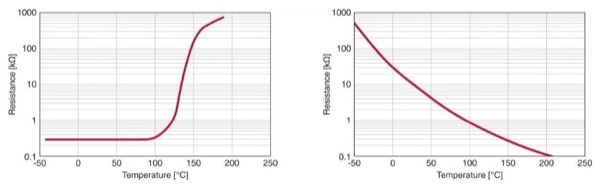
Figure 1: Resistance characteristics of PTC and NTC thermistors. On exceeding a specific temperature, PTC thermistors (left) show a very sharp rise in resistance, making them suitable as temperature limit sensors. NTC thermistors, on the other hand, exhibit greater linearity and are therefore suitable for temperature measurement.
Reliable temperature monitoring with PTC sensors
PTC thermistors with their very steep curves are very suitable for the monitoring of temperature limits and consequently for switching on a fan when a particular temperature is reached. A further advantage of the PTC temperature characteristic is that PTC thermistors can be connected in series and thus, in their function as temperature sensors, can very easily monitor several hot spots. As soon as one of these PTC sensors in a series connection exceeds the specified limit temperature, the circuit switches to the high-ohmic state. This principle can be applied, for example, in notebooks, in order to monitor the main processor, the graphics processor and any other heat emitting components using SMD PTC sensors.
A further application of PTC sensors is the thermal monitoring of the windings in three-phase motors. For this purpose, TDK offers special types that are assembled accordingly and which can be easily integrated into the windings. Figure 2 shows PTC sensors for limit temperature monitoring.
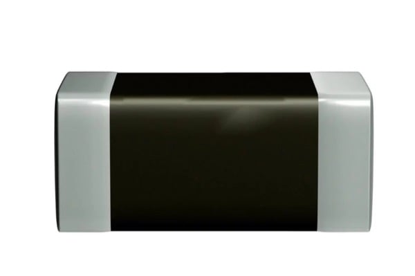
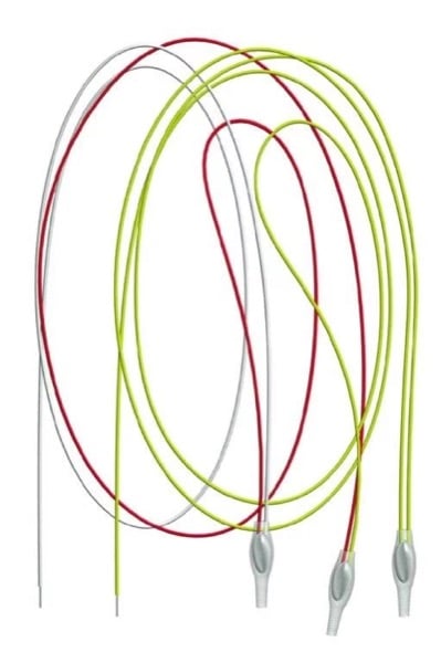
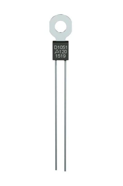
Figure 2: Different versions of EPCOS PTC sensors. From top to bottom: SMT-PTC temperature sensor for mounting on printed circuit boards, PTC sensors for integration in motor windings, PTC sensor with lug for mounting onto heatsinks.
Switching principle for the recording of limit temperatures
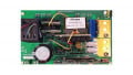
Figure 3 shows a simple circuit with two series-connected PTC sensors for the monitoring of limit temperatures. TR1 and the two PTC sensors form a voltage divider which supplies the non-inverting input of the operation amplifier that functions as a comparator. TR1 is set in such a way that its maximum value corresponds to about twice that of the resistance of the PTC series connection at 25 °C. For fine adjustment, the value of TR1 can be set accordingly. In the cold state, a potential is present at the non-inverting input which is more negative than the reference potential at the inverting input. This means that a negative voltage is present at the comparator output. If one or both PTC sensors reaches the limit temperature, the potential at the voltage divider changes and the comparator switches to a positive output signal, which trips the transistor.
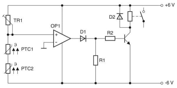
Figure 3: Circuit for monitoring temperatures with PTC sensor. Circuit for monitoring two hot-spots: When the limit temperature is exceeded a fan can be switched on, for example.
Detecting two temperatures with one sensor
In addition to PTC thermistors, NTC thermistors can also be used for temperature monitoring. This applies in particular when a higher demand is made on the linearity of the characteristic.
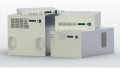
How such a temperature monitoring is reliably implemented using NTC sensors is shown in the following practical example for the detecting of two temperatures in a high-performance audio end stage. In order to keep the housing dimensions as small as possible, the eight output transistors in TO-3 packages have been mounted together with the emitter resistors on a combined cooling fan unit. Four separate heatsinks are used here which are arranged point-symmetrically to one another. For each heatsink two power transistors have been installed (Figure 4).
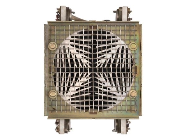
Figure 4: Combined fan/cooling unit. In this design, each of the four heatsinks must be thermally monitored.
Special attention is paid to the thermal monitoring of the output transistors. Because these are located on four heatsinks that are both electrically and thermally insulated from one another, each heatsink must be monitored individually. The reason for this is that, despite adequately dimensioned transistors, the tolerances can result in a slightly uneven load distribution. The thermal monitoring must take place in two stages: as soon as one or more heatsinks reaches a temperature of 85°C, the fan must be switched on, and on reaching a temperature of about 100°C a load must be shed.
This dual function is to be performed with a single temperature sensor. The K45 or M703 series of EPCOS NTC sensors are very well suited for this purpose (Figure 5).
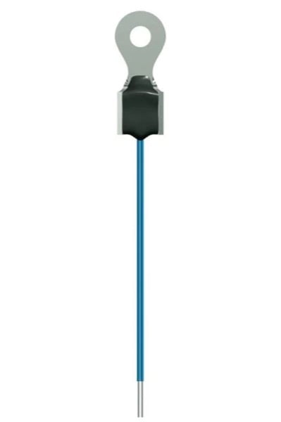
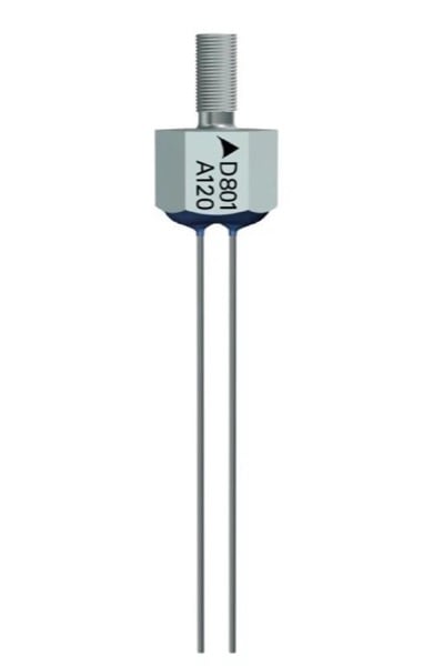
Figure 5: EPCOS NTC sensors for heatsink mounting
Thanks to the lug (top) or the threaded bolt (bottom), these EPCOS NTC-sensors offer a very good thermal contact with the heatsink. A K45 EPCOS NTC thermistor with an R25 of 10 kΩ was selected for each of the four heatsinks (B57045K0103K000). According to the data sheet, at 85 °C the resistance ratio RT/R25 is 0.089928, which produces an resistance of about 900 Ω. At 100 °C, this results in a value of about 550 Ω. For the dual temperature measurement a circuit with two comparators is necessary. The complete circuit as implemented is shown in Figure 6.
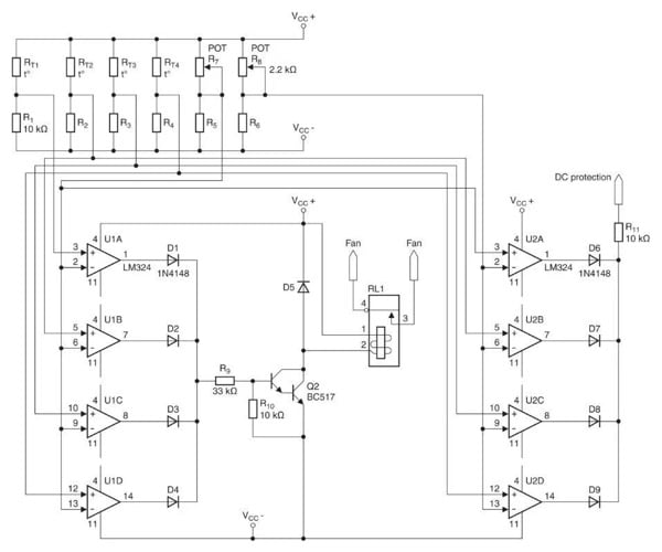
Figure 6: Double temperature protection of an audio end stage. With this circuit, four heatsinks can be thermally monitored. Above a temperature of 85°C the fan is activated. If, under unfavorable conditions, temperature even reaches 100°C, the load is rejected. To do this, the DC voltage protection circuit receives a positive signal, causing its relay to trip.
The reference values for the two switching thresholds are set with the two trimmers R7 and R8 (2.2 kΩ each). These are set at the levels of 900 Ω or 550 Ω already mentioned. For the eight necessary comparators (U1A – U1D and U2A – U2D) economical LM324 amplifiers have been used.
In a test lasting several hours under full load in jumper mode the fan switched on reliably at 85 °C. As the system is relatively slow in thermal terms, there was no need for a hysteresis circuit connection of the comparators which would normally be the case. In order to test the isolation at high temperature, the end stage was subsequently tested with the fan disconnected. The safety disconnection temperature measured was 103 °C. By means of fine adjustment with R8 it was possible to set this value to exactly 100°C.
Thanks to the very wide range of EPCOS NTC and PTC sensors with different characteristics and a wide variety of designs and fixing options, the thermal management of almost every conceivable application can reliably be implemented.
About the Author
Christophe Jehle is the head of Products & Technologies at TDK Electronics, an electronics company based in München, Bayer, Germany that develops, manufactures and markets electronic components and systems, focusing on fast-growing leading-edge technology markets, which include automotive electronics, industrial electronics and consumer electronics as well as information and communications technology.
This article originally appeared in the Bodo’s Power Systems magazine.
Related Content