Facebook
 Google
 GitHub
 Linkedin
The Fundamentals of Capacitors in AC Circuits
Learn about the fundamentals of capacitors in AC circuits, including the concept of capacitive reactance, capacitor behavior in series and parallel configurations, and how power is influenced in capacitive circuits.
Capacitors in AC circuits play a crucial role as they exhibit a unique behavior known as capacitive reactance, which depends on the capacitance and the frequency of the applied AC signal. Capacitors store electrical energy in their electric fields and release it when needed, allowing them to smooth voltage variations and filter unwanted frequencies. They are used in various applications, including power factor correction, energy storage, and signal coupling.
Image used courtesy of Adobe Stock
Figure 1 illustrates a capacitor circuit and a full cycle of alternating voltage and current in a capacitive circuit.
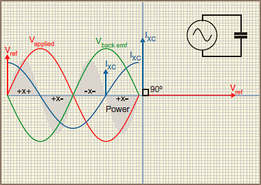
Figure 1. Capacitive AC circuit behavior. Image used courtesy of Amna Ahmad
Without resistance in the circuit, the capacitance charges according to the rate of change of the applied voltage. That means that when the voltage changes the most, the current in the capacitor will be the greatest. When the voltage reaches its maximum value, the current will be zero, but as the voltage decreases, the current changes direction.
As the current is already at maximum positive flow when the voltage sine wave crosses zero, going positive, it seems that the current comes first, before the voltage, so in a capacitive circuit, the current leads the voltage.
For any purely capacitive circuit, the current leads the applied voltage by 90°E, as shown. The phasor diagram shown in Figure 1 shows a current phasor leading the voltage by 90°.
Capacitive Reactance
When an ac voltage is applied to a capacitor, it is continually being charged and discharged, and current flows in and out of the capacitor at a regular rate, dependent on the supply frequency. An AC ammeter connected in the circuit would indicate a current flowing through the capacitor, but the capacitor has an insulating dielectric between the two plates, so it is a displacement current that the ammeter records.
The value of this current is affected by the applied voltage, the supply frequency, and the capacity of the capacitor.
Since a capacitor reacts when connected to ac, as shown by these three factors, it is said to have the property of reactance — called capacitive reactance. The symbol is XC, and the unit is the ohm:
\[X_{C}=\frac{1}{2\pi fC}\]
Where
XC = capacitive reactance (Ω)
f = frequency (Hz)
C = capacitance (Farad)
Example 1: Determine the current drawn by a 20 µF capacitor when it is connected to a 250 V 60 Hz power supply.
\[X_{C}=\frac{1}{2\pi fC}=\frac{1}{2\times\pi\times60\times20E-6}=132.7\Omega\]
\[I=\frac{V}{X_{C}}=\frac{250}{132.7}=1.884\,A\]
Capacitors in Series
When two capacitors are placed in series, the effect is as if the distance between the outside plates were increased and the capacity is therefore decreased. On an alternating current supply, this effectively increases the opposition to a current flow in a similar fashion to that of resistors placed in series:
\[X_{Ctotal}=X_{C1}+X_{C2}+X_{C3}\cdot\cdot\,\cdot+X_{Cn}\]
Example 2: Calculate the capacitive reactance and current for a 10 µF capacitor connected to a 200 V 60 Hz supply. Determine the new current when the existing capacitor is connected in series with another 10 µF capacitor.
\[X_{C}=\frac{1}{2\pi fC}=\frac{1}{2\times\pi\times60\times10E-6}=265.4\Omega\]
\[I=\frac{V}{X_{C}}=\frac{200}{265.4}=753.4mA\]
\[I=\frac{V}{X_{C1}+X_{C2}}=\frac{200}{265.4+265.4}=376.65mA\]
Capacitors in Parallel
When two capacitors are placed in parallel, it is as if the area of the plates were increased, and the total capacity is increased. The current flow is therefore increased. Each parallel path consumes current according to its opposition to the current flow. Two equal-sized capacitors would each draw their normal current, but the total current flow would be double the current flow to a single capacitor.
The total opposition to the current for the parallel network is:
\[\frac{1}{X_{Ctotal}}=\frac{1}{X_{C1}}+\frac{1}{X_{C2}}+\frac{1}{X_{C3}}+\cdot\cdot\cdot+\frac{1}{X_{Cn}}\]
In the following example, the same capacitor values and supply voltage have been used as an Example 2 to compare the results. Note: The results will differ.
Example 3: Two 10 µF capacitors are connected in parallel to a 200 V 60 Hz supply. Determine the following:
Current flowing through each capacitor
The total current flowing.
\[X_{C}=\frac{1}{2\pi fC}=\frac{1}{2\times\pi\times60\times10E-6}=265.4\Omega\]
\[I=\frac{V}{X_{C}}=\frac{200}{265.4}=753.4mA\]
\[X_{Ctotal}=\frac{1}{\frac{1}{X_{C1}}+\frac{1}{X_{C2}}}=\frac{1}{\frac{1}{265.4}+\frac{1}{265.4}}=198.9\Omega\]
\[I=\frac{V}{X_{C}}=\frac{200}{132.65}=1.51\,A\]
Power in a Capacitive Circuit
As with inductors, capacitors charge and discharge, and the energy stored in the capacitor in the one-quarter cycle is returned in the next quarter cycle, so the average power in a purely capacitive circuit is zero.
In Figure 1, the shaded power waveform results from multiplying the instantaneous voltage and current values. When both are positive, the capacitor is charged; when both are negative, the capacitor is charged in the opposite polarity. However, the charge is returned to the power supply when one is positive, and the other is negative. No power is consumed because the charge is the same size as the discharge.
There is as much power curve above the zero line as below it. The average power in a purely capacitive circuit is zero.
Takeaways of Capacitors in AC Circuits
Capacitors in AC circuits are key components that contribute to the behavior of electrical systems. They exhibit capacitive reactance, which influences the opposition to current flow in the circuit. Understanding how capacitors behave in series and parallel connections is crucial for analyzing the circuit's impedance and current characteristics. Additionally, understanding the power dynamics in capacitive circuits is essential to analyze energy transfer and efficiency. By understanding these concepts, one can effectively analyze and design AC circuits involving capacitors.