Facebook
 Google
 GitHub
 Linkedin
The Fall-of-Potential Method vs. the Clamp-on Tester Method
Learn about the pros and cons of the fall-of-potential method and the Clamp-on tester resistance method.
Both the fall-of-potential method and the clamp-on tester method have advantages and disadvantages. Knowing their limitations and correct applications allows us to make accurate grounding resistance measurements.
Advantages and Disadvantages of the Fall-of-Potential Method
The main advantage of the fall of potential method is its accuracy. No other way of measuring ground resistance is more accurate. You may change the span D at will and compare the resistance outcomes until achieving reasonable figures.
The disadvantages are as follows:
-
The grounding electrode must be disconnected to get the most out of the method. Otherwise, there will be multiple test current return paths. This disconnection is usually very difficult or impossible to accomplish.
-
It requires a lot of space because the span D can be huge.
-
It is labor-intensive, requiring a lot of time and a crew. It involves placing several electrodes at various distances, as well as doing measurements, calculations, and making decisions.
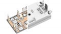
The Clamp-On Tester
The clamp-on tester is another method of determining the earth resistance of a grounding electrode. The clamp-on tester does not require the disconnection of the grounding electrode from the system, and there is no need for reference electrodes or additional cables.

Image courtesy of Megger.
The instrument applies a known voltage to the grounding system and measures the resulting current magnitude. Knowing the voltage and the current, and using Ohm’s law, it computes and displays the value of resistance in ohms. It is essential to keep in mind that, for proper operation, there must be a loop resistance to measure.
The clamp-on tester has particular applications and is not suitable for commissioning new installations. Some typical applications are:
- Utility poles
- Service entrance or meter
- Street lighting
- Lightning protection
- Street cabinets
- Telephone pedestals
- Cell towers
- Pad-mounted transformers
The user must closely follow the manufacturer’s recommendations to operate the instrument properly.
How Low Should the Grounding Resistance Be?
There is no rule of thumb to indicate what the correct grounding resistance value is. It should indeed be as low as possible. However, it is often challenging to obtain low resistance, especially with high resistivity soil.
The right thing to do is to perform a study tailored to the particular needs of the system and the electrical equipment involved. It is common for manufacturers of electrical equipment to recommend a resistance value for the correct operation of their equipment.
For those facilities regulated by the National Electrical Code (the NEC), this does not establish specific requirements for grounding resistance. The NEC only specifies that if a rod, pipe, or plate grounding electrode has a resistance to earth of 25 Ω or less, a supplemental electrode shall not be required.
The NEC prohibits the use of the earth as the sole return path for ground-fault current. The ground-fault current flows through the equipment grounding conductor and reaches the source via the grounded service conductor. For this reason, the ground resistance value is not as relevant for clearing ground faults. Even with a little ground resistance, approximately 95% of the ground-fault current would travel through the grounded service conductor. Low resistance is useful, however, to keep the system neutral at earth potential.
For a residential or commercial facility, with single-phase 120/240 V loads, less than 25 Ω will be alright. If the loads are mainly single-phase in a three-phase system, the maximum recommended resistance is 5 Ω. But if the loads are three-phase, the maximum resistance is 1 Ω.
The electrical industry specifies 1 Ω for transmission substations and from 5 Ω to 1 Ω for distribution substations. The criteria followed in the electrical industry to calculate substation grounding mats are rigorous and take into account many factors that are not necessarily solved by a simple typical grounding resistance value. The electrical sector places considerable emphasis on the use of computer programs to calculate the design parameters of substation ground systems.
In medium and high voltage electrical transmission and distribution systems, the ground-fault current travels through the ground and can reach thousands of amps. If the resistance of the ground mat is high, the voltage may rise to values on the order of kilovolts, posing a dangerous condition for people and equipment.
The standard practice for protection against lightning strikes is a grounding resistance of 1 Ω or less.
A Review of the Fall-of-Potential Method
The opposition to the flow of current through the soil is the main component of the resistance to earth.
The resistance of a grounding electrode or grounding mat is computed during the design stage. This calculation produces an approximate value because the formulas include constants that are not genuinely constant, like the soil resistivity.
It is necessary to measure the actual value of the earth’s resistance after the completion of the work. Subsequent periodic measurements are convenient to ensure that the resistance value has not increased considerably. Degradation may occur if the soil conditions change or if the grounding electrode deteriorates.
It is essential to keep in mind that the results of the measurements are approximate, and they depend on the proper use of the instruments and an appropriate selection of the location for the reference rods.
The fall-of-potential method is the most reliable, but it is also complicated. It uses a couple of reference ground connections and a source of AC or DC current that circulates through the ground under test.
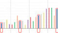
Measuring the voltage drop along a straight line and the current through the ground, simultaneously, and applying Ohm's law, a resistance vs. distance graph is plotted.
The approximate resistance to ground is the one on the flat portion of the curve. This flat part is at about 62% of the distance between the grounding electrode and the current reference rod.
There are several manufacturers of self-contained test instruments that make use of the fall-of-potential method.
Clamp-on testers are easy to use, but strictly following the manufacturer’s instructions as they are intended for specific applications.
There is no correct grounding resistance value to the target. The most appropriate amount should be decided for each particular case. Typical figures are only a recommendation.