Facebook
 Google
 GitHub
 Linkedin
TMR vs. Shunt Sensors
There was a time when shunt solutions were considered the safe choice in sensor technology. Let's take a look at how things have changed.
There was a time when shunt solutions were considered the safe choice in sensor technology, but the world has changed. The days of trying to piece together inexpensive shunt architectures are over. As accuracy requirements continue to go up, traditional shunt solutions have lost cost-effectiveness as total solution costs increase dramatically.
Shunt Challenges
Shunt designers are routinely faced with a balancing act to select the correct combination of resistor, operational amplifier, and implementation topology. Designing an accurate and cost-effective shunt-based current sensing solution requires a substantial engineering effort.
For instance, using a shunt-resistor in high-voltage systems for measuring high-side current requires an isolated op-amp which complicates and increases cost. Tunnel MagnetoResistance (TMR) architecture simplifies the circuit design while providing built-in galvanic isolation. Its construction provides inherent isolation because the active circuitry on the die does not electrically connect outside of the molded package.
Another concern is the supply chain, which is driving new ways to meet current sense requirements. Supply chain issues mean a complicated architecture like shunt incurs significant risk. For example, many of the zero-drift amplifiers needed for the shunt solution now take a year to acquire. More parts mean more things can go wrong, more reliance on the supply chain, and, ultimately, more risk.
TMR vs. Shunt
In shunt-based sensing, a small-value shunt resistor (typically less than one Ohm) is placed in series with the load. Per Ohm’s Law, a small voltage on two sides of the shunt is proportional to the current draw of the load. As the max current increases, the shunt resistive value must decrease to minimize the excessive power losses due to heat dissipation and temperature rise.
The small voltage must be amplified in many cases to provide enough resolution, SNR, and accuracy (Figure 1.) However, low-price shunt sensors can suffer from power dissipation, error over temperature due to TCR, and low output range. Hence, a good resistor and an isolated zero-drift amplifier may no longer be the most cost-effective or simplest solution.

Figure 1. An isolated shunt amplifier. Image used courtesy of Bodo’s Power Systems [PDF]
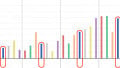
In high-performance applications, shunt performs well in some categories (bandwidth) and poorly in others (noise). (See Figure 2)
Figure 2. CT430 TMR vs. Shunt.
| Shunt-Based Current Sensors | CT430 | |
| Total FS Error | ±0.5%-5% | ±0.5%-1% |
| Temperature FS Error | ±0.21% - ±1.19% | ±0.5% |
| Non-Linearity FS error | ±0.03% - ±0.3% | 0.1% |
| Offset Error | 0.06A-2.3A | 0.083A |
| THD | -34 to -50dB | -46dB |
| SNR | 14–31dB | 31dB |
| Application Noise StdDev | 2.6 – 16.3 | 2.53 |
| CMRR FS Error | 0.02% to ± 2.5% | N/A |
| Bandwidth | 50kHz-1.7MHz | 1MHz |
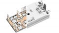
TMR also features a simpler architecture in isolated applications than shunt-based systems (Figure 3).
Design Considerations
Historically, hall effect sensing has been considered an alternative to shunt, but due to inferior temperature performance, linearity errors, and offset errors, it was not a viable alternative. Here's how they stack up.
Magnetic - Hall Effect
The operation relies on the hall effect, shown in Figure 4(a), where current (I) flowing through a conductor in the presence of an applied magnetic field (B) generates a transverse hall voltage (UH) that is a function of the current, the magnetic field, the thickness of the conductor and the charge carrier density.
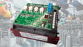
Figure 5 shows a typical EV or HEV arrangement where the shunt is placed in the battery return path. The shunt resistor is part of a module that also includes a battery management IC to measure the voltage across the shunt and communicates with the vehicle network over the industry-standard CAN bus. Note that the current flow can be positive or negative.
The resistance of an “ideal” shunt resistor does not change with time, current, or operating temperature; this is not true for a real-world device. For example, any resistor dissipates power according to the equation P = I2R. As I increases, so too does the temperature. In a real component, a change in temperature causes a change in the value of R, characterized in a resistor data sheet as the temperature coefficient of resistance (TCR). Additionally, component aging causes the resistance to change over time, and a real-world device also exhibits parasitic inductance and capacitance. At low currents, error may occur due to thermal electromotive force (EMF) — a voltage in the microvolt (μV) range caused by temperature variations across the shunt resistor.
Hall Effect Versus Shunt Resistor
Hall effect sensors can measure both DC and AC current, have inherent galvanic insulation, low power loss, and thermal decoupling from the power electronics, yet their historic weaknesses: low bandwidth; output drift and non-linearity over temperature; and self-heating at high currents that lead to a low overcurrent capability. The magnetic core exhibits hysteresis, and saturation leads to non-ideal offset and linearity characteristics. Additionally, the core contributes to a comparatively large size and weight.
On the other hand, a shunt-resistor system can feature high bandwidth, and good performance under overcurrent conditions. They also can measure both AC and DC currents. Since there’s no magnetic core, they are lightweight, saturation and hysteresis do not occur, and it’s less prone to noise in the signal caused by EMI. A shunt-based system has more robustness to vibration in applications such as electric vehicles.

Image used courtesy of Bodo’s Power Systems [PDF]

Figure 3. Shunt based design vs. Crocus CT45x TMR Design, including bill of materials. Image used courtesy of Bodo’s Power Systems [PDF]

Figure 4. The hall effect (a) and a hall effect current sensor (b). Source: Isabellenhütte The Hall effect forms the basis of a current sensor, shown in Figure 4(b). A Hall element is mounted in the gap in a ferrite magnetic core placed around the current conductor. The Hall voltage indicates the DC magnetic flux, leading to a measurement of the DC current in the conductor. Image used courtesy of Bodo’s Power Systems [PDF]
Shunt-based sensing technology can be an efficient solution for vehicular and stationary applications. hall effect magnetic components have their place, but shunt-based solutions are preferable where precise performance over a wide temperature range is a priority.
Figure 6 illustrates the shunt-based system’s accuracy over temperature versus a hall-effect system.

Figure 5. Shunt current measurement. Source: Isabellenhütte. Image used courtesy of Bodo’s Power Systems [PDF]

Figure 6. Accuracy comparison versus temperature. Source: Isabellenhütte. Image used courtesy of Bodo’s Power Systems [PDF]
Advantages of TMR Technology
TMR technology has advantages over both shunt resistors (with added amplifiers and digital isolators) and hall effect-based sensing solutions, especially for battery-powered systems. TMR also offers lower power consumption, better thermal stability, better resolution, and higher sensitivity.
Amazingly, TMR provides 1000 times more sensitivity than the hall effect while consuming only a few microampere currents. With its uniquely positive features, the TMR sensor has the potential to replace hall effect sensors in most applications. Engineers who have been using a hall-based sensor for current sensing now see it can offer a significant advantage for their system on accuracy, bandwidth, latency, and overall efficiency.
The main advantages over hall and shunt-based solutions include:
- High SNR (5-mA resolution in current sensors)
- Low power consumption
- Temperature stability (less than 40 ppm/°C)
- Programmable overcurrent detection and fault pin to provide current information to the MCU
- Measure of both positive and negative current with bidirectional sensing
Figure 7 shows a waveform comparison of a hall sensor and TMR sensor under the same application conditions. You can see the TMR waveform is clean and accurate to the peak measurement levels. The hall sensor provides a noisy signal with less accurate measurements.

Figure 7. TMR sensor vs. Hall-based sensor (Source: Crocus Technology). Image used courtesy of Bodo’s Power Systems [PDF]
Key Takeaways of TMR Technology
TMR is less susceptible to temperature changes and boasts low power consumption, high signal-to-noise ratio, better linearity, and needs no additional flux concentrator structure. The output of TMR sensors is 1000 times higher than that of a hall element.
While shunt is preferable to the hall effect, when accuracy is paramount, shunt-based current sensors tend to suffer from CMRR error. TMR coreless current sensors are not only smaller in size and simpler to design than shunt, but they also provide 99% immunity to stray magnetic fields, dramatically improving accuracy. And with shunt resistors, you still are faced with a tradeoff of precision and dissipated power, as well as voltage drops that may not be acceptable for very low voltage, high current applications.
Finally, the complicated architectures of shunt and hall effect could mean supply chain issues, leading to significant risk.
This article originally appeared in Bodo’s Power Systems [PDF] magazine.
Featured image used courtesy of Adobe Stock