Facebook
 Google
 GitHub
 Linkedin
Smart Substations and Digitalization—Part 3: Comms and Data Integration
This article focuses on practical implementation details for communications and data integration in smart substations and reviews predictive maintenance concepts with asset-specific techniques.
Digitalized substations are reshaping protection, control, and asset management by turning once-isolated devices into synchronized, data-rich systems. The shift rests on interoperable communications, deterministic timing, and analytics that convert continuous condition data into actionable maintenance decisions.

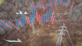
Substation control room. Image used courtesy of Siemens
Communication and Data Integration
Modern substation data exchange increasingly relies on IEC 61850, which separates standardized information models from transport mappings to enable vendor interoperability.
Station-bus messaging (GOOSE) and client/server services (MMS) share the same logical data structures as process-bus sampled measurements (SV), allowing protection IEDs, bay controllers, and gateways to consume consistent semantics regardless of the transport. Key parts include IEC 61850-8-1 for MMS and GOOSE, and IEC 61850-9-2 for Sampled Values over Ethernet, which remains the reference for SV dataset definition, buffering, and link redundancy behavior.
Where synchrophasors or wide-area applications are involved, IEC TR 61850‑90‑5 provides routable profiles for GOOSE and SV, and a method for carrying IEEE C37.118 phasor streams within the 61850 ecosystem, enabling coherent protection and monitoring beyond the substation perimeter.
Brownfield integration still requires coexistence with entrenched protocols, such as DNP3 and Modbus. DNP3 remains common between RTUs/IEDs and SCADA masters, supporting secure time-stamped events and unsolicited reporting; updated profiles are standardized in IEEE 1815. Modbus remains in use for simple register-based exchanges and is now complemented by a security profile that wraps transactions in TLS.
Practical interoperability is often achieved with protocol gateways that translate between IEC 61850 common data classes and legacy ASDU/object models. IEC TS 61850‑80‑1 provides guidance on mapping CDC-based data to IEC 60870‑5‑101/104, a common requirement for control center links.
Time Synchronization
Deterministic time synchronization is fundamental to event correlation, fast protection, sampled values, and synchrophasor alignment. IEC 61850-9-3 defines a substation-grade Precision Time Protocol (PTP) profile based on IEEE 1588 (IEC 61588), targeting microsecond-level accuracy and specifying clock roles, intervals, and performance across transparent/boundary clocks.
Utilities are increasingly deploying PTP grandmasters with redundant network paths and PRP/HSR topologies for zero-time recovery. IEEE 1588‑2019 preserves PTP’s sub‑microsecond objectives and adds improved asymmetry handling, while IEC 62439‑3 defines PRP/HSR redundancy used widely in digital substations.
Precise time also needs to be carried with the data. IEC 61850 data attributes include a timestamp (t) and a quality (q) bitstring. TimeQuality flags (such as clock not synchronized or accuracy class) inform receiving devices how to process and align events. This is essential for sequence‑of‑events (SOE) analysis and for distinguishing test/substituted values from valid measurements.
For disturbance analysis and cross‑vendor exchange, COMTRADE (IEC 60255‑24) remains the standard file format for oscillography and event data, now supporting single‑file CFF packaging with multiple numeric encodings.
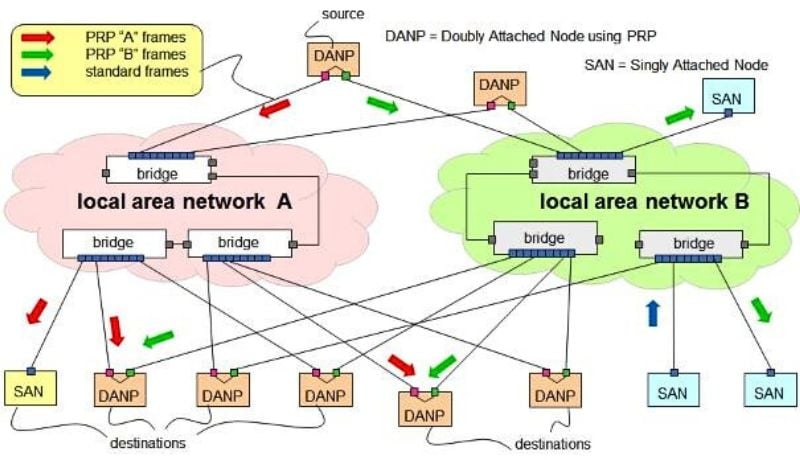
Figure 1. PRP network operation. Image used courtesy of Wikimedia Commons
Predictive Maintenance Concepts
From Time‑Based to Condition‑Based Maintenance
Calendar-based maintenance is simple to administrate but often misallocates effort: some assets are serviced without need, while others degrade between intervals. Reliability‑centered maintenance (RCM) reframes tasks around failure modes, consequences, and evidence, promoting monitoring and diagnostics over fixed‑interval overhauls. IEC 60300‑3‑11 provides the generic RCM approach used across industries and aligns preventive tasks with actual failure behavior.
In parallel, modern asset management frameworks (ISO 55000:2024) emphasize value, risk, and performance over the full life cycle, encouraging data‑driven decisions that integrate condition, criticality, and cost.
Condition indicators feed composite health indices that are trended over time. Typical inputs include thermal stress metrics, dissolved gas rates in oil, breaker mechanism signatures, contact wear markers, and partial discharge magnitudes/patterns. Translating these into a health score enables a fleet‑level view, while risk‑based prioritization multiplies probability (condition) by consequence (asset criticality and system impact) to stage interventions where they matter most—consistent with contemporary asset‑management principles.
Asset‑Specific Predictive Techniques
Transformers: Thermal aging models remain central because insulation life dominates transformer end‑of‑life. IEEE C57.91 details thermal modeling and loading guidance, relating hot‑spot temperature to loss‑of‑life and clarifying how ambient, cooling stage, and load profiles influence aging. In a digital substation, online winding hot‑spot estimation and top‑oil sensors continuously feed these models for risk‑aware loading and maintenance scheduling.
Dissolved Gas Analysis (DGA) complements thermal monitoring: IEC 60599 provides interpretation rules for gas ratios/thresholds and trending, while IEC 60567 describes extraction and chromatography methods that ensure consistent, comparable datasets. Combining DGA fault signatures with rate‑of‑change indicators helps detect incipient faults such as overheating, partial discharge in oil, or arcing, well before protection operates.
Circuit Breakers: For breakers, wear accumulates in mechanisms and interrupters rather than bulk insulation. Operation count is the simplest indicator. However, richer signatures provide earlier warnings.
- Timing and contact travel traces identify drag, misalignment, and lubrication issues.
- Trip/close coil current profiles reveal sluggish mechanisms, low control voltage, or sticking latches.
- Dynamic contact resistance highlights arcing contact erosion.
IEC 62271‑100 establishes performance and test concepts for high‑voltage AC breakers, while coordinated field studies document in‑service monitoring that captures mechanical, electrical, and even RF emissions around switching, linking anomalies (such as late re‑ignitions) to root causes such as grading capacitor defects or incorrect controlled switching settings.
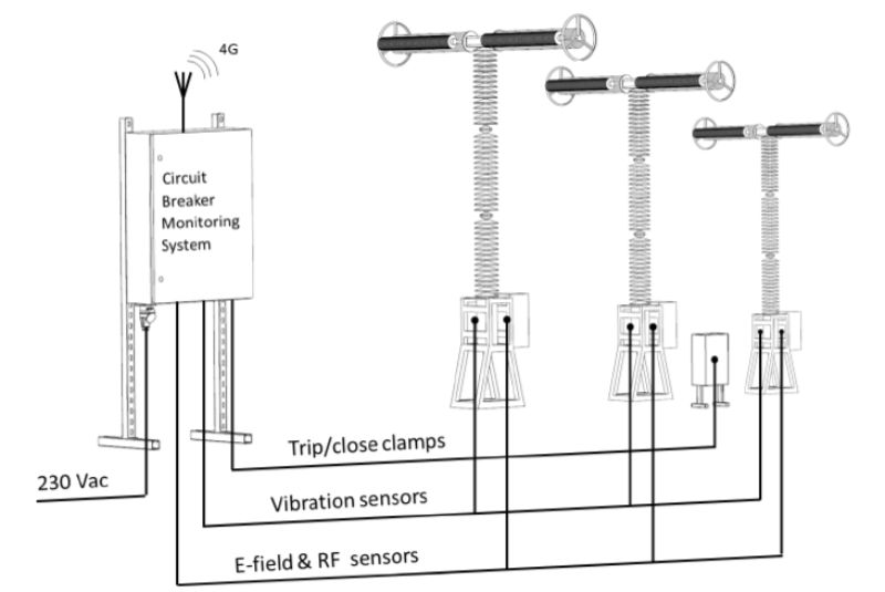
Figure 2. Circuit breaker monitoring. Image used courtesy of CIGRE
Cables and GIS: Partial discharge (PD) is the primary early‑warning phenomenon in high‑voltage cable systems and gas‑insulated switchgear. IEC 60270 remains the foundational PD measurement standard, while the IEEE 400 family provides field test guidance for shielded power cables—IEEE 400‑2023 (overview), 400.2‑2024 (VLF methods), and 400.3‑2022 (PD field diagnostic testing). Trending PD inception levels, phase‑resolved patterns, and site‑located defects support planned outages and targeted repairs of joints/terminations.
In GIS, UHF PD detection has become standard practice for factory/site tests and online monitoring; CIGRE TB 654 details sensitivity verification and application nuances, and IEC 62271‑203 defines product requirements for GIS above 52 kV that form the basis for acceptance and lifecycle monitoring programs.
Integration Patterns That Keep Systems Deterministic
A few architectural patterns emerge in successful digital substation deployments:
Engineer time first. Distribute a PTP grandmaster per substation section, use boundary/transparent clocks in hardened switches, and validate end‑to‑end accuracy against required protection classes. Apply PRP or HSR so time distribution and SV/GOOSE survive single failures without switchover transients.
Keep data models consistent. Engineer SCL files as the “single source of truth” for logical nodes, datasets, and reports, then leverage gateways only to bridge essential legacy paths (such as DNP3 outstation to SCADA) while preserving semantics and timestamps. Use IEC TS 61850‑80‑1 mappings where 101/104 are mandated upstream.
Treat quality as data. In historian and analytics pipelines, ingest t and q attributes alongside values so health indices and alarm logic can de‑rate questionable or test data and avoid misleading trends during commissioning or fallback modes.
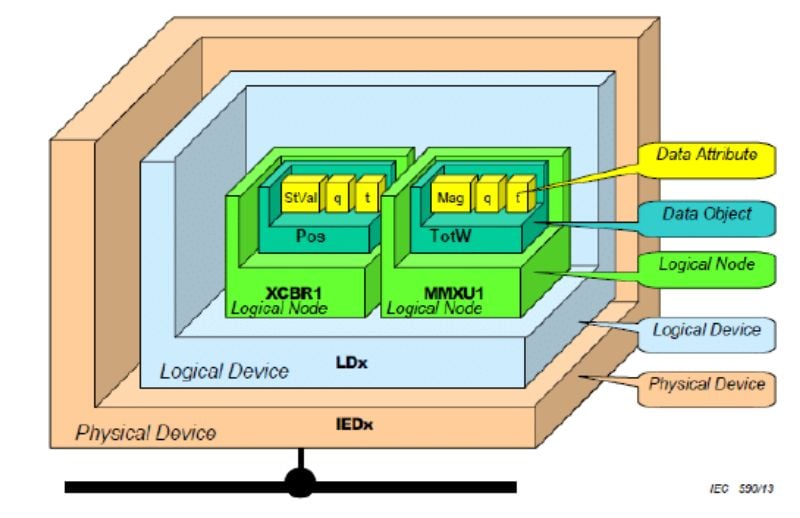
Figure 3. IEC 61850 data model. Image used courtesy of Scada Protocols
Conclusion
Smart substations succeed when communications, timing, and analytics are engineered as an integrated system. IEC 61850 provides common semantics across MMS, GOOSE, and Sampled Values and extends to routable synchrophasor transport. Protocol gateways and IEC TS 61850‑80‑1 maintain interoperability with brownfield fleets. IEEE 1588 with the 61850‑9‑3 profile plus PRP/HSR delivers the determinism needed for fast protection and reliable event correlation.
On the maintenance side, RCM and ISO‑aligned asset management frameworks encourage replacement of calendar‑based routines with continuously updated health indices and risk‑based prioritization. Applying asset‑specific techniques—thermal models and DGA for transformers, signature‑based monitoring for breakers, and PD trending for cables and GIS—turns continuous data into improved predictability and better‑timed interventions. The result is a substation that not only speaks in a common language but also decides and acts based on evidence, improving reliability while managing costs.