Facebook
 Google
 GitHub
 Linkedin
Calculating DC-Link Capacitance for xEV Powertrains
There are many formulas to calculate DC-link capacitance in pulse-width modulated inverters of electric vehicles. This article illustrates a fast and simple path to a practical solution.
This article is published by EEPower as part of an exclusive digital content partnership with Bodo’s Power Systems.
There are many formulas to calculate DC-link capacitance in electric vehicle pulse width modulated inverters.
A capacitor in the intermediate circuit of the automotive inverter for storing and buffering energy is a DC-link capacitor (Figure 1 outlined in green). The main target of the DC-link capacitor with this capacitance is to absorb sufficiently current ripple generated by the fast switching 3-phase inverter power stage, which is connected to the motor through short cabling or bus bars.

Figure 1. Simplified Power Train Circuit Diagram schematic and a Capacitors currents flow example. Image used courtesy of Rambow Technology and Bodo’s Power Systems [PDF]
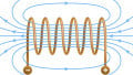
The capacitance is chosen to keep the maximum DC-link voltage ripple under control and, at the same time, to improve system energy density. These capacitors typically operate at high voltages extending from 400 VDC to 800 VDC. The automotive industry is well known for stipulating components that guarantee outstanding reliability when operating under the influence of heavy stress, e.g., at extremely high temperatures, vibration, and humidity. For all inverters, it is true that the DC-link capacitor, as an A-component, is key to the design, reliability, and, ultimately, success. There are many more or less complicated calculation formulas available for DC-Link capacitance in pulse-width modulated electric vehicle inverters (Figure 2).

Figure 2. PWM - the duty cycle is varied in a sinusoidal manner. Image used courtesy of Rohde & Schwarz and Bodo’s Power Systems [PDF]
In automotive power trains, the DC-link film capacitor is mounted directly to single switches or semiconductor power modules (if B6 or half bridges are used) with very low ESL and ESR values (Figure 1 in green). The vicinity of the capacitor to the power module is one essential target to minimize stray inductance between the power stage and the capacitor itself.
Applying an overlapping busbar concept keeps the ESL as low as possible, while the ESR is determined by the inner construction of the capacitor itself. Even a few nanohenries of stray inductance in the capacitor current path raises the impedance at the switching frequency to levels that negate their effectiveness. Large ripple voltage indicates a large ripple current flowing in bulk capacitors and can cause excessive power dissipation in the ESR. Before becoming thermally limiting, properly selecting a capacitor and its location can positively affect the car’s EMC robustness. If ripple voltages and corresponding currents are kept low, the potential influence on safety-relevant systems in the car is drastically reduced, too, so no interference occurs in the vehicle's electrical system that could affect other functional modules.
As frequency increases, the battery and cable parasitic source Inductance cause the impedance to increase. The DC-link capacitor impedance goes down, so it becomes the preferable path for high-frequency AC to circulate capacitor ripple current (ICrms).
Load current (IMrms) magnitude and the resulting capacitor ripple current (ICrms), duty cycle (dc or m; in worst-case m=0.5), switching frequency (f), and temperature (T(C)) are typical factors that determine the magnitude of the ripple voltage across the terminals of the capacitor. Since the ripple voltage amplitude is directly proportional to the output load current, the maximum current ripple amplitude occurs at maximum output load, which is unsurprising. The solid curve in Figure 3 shows the calculated AC rms ripple amplitude that generates the considered loss in the capacitor. It reaches a maximum of 50% duty cycle. The chart [Source: TI] shows how this magnitude falls off on either side of 50%.
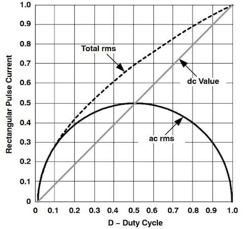
Figure 3. Magnitude drops on either side of 50%. Image used courtesy of Texas Instruments and Bodo’s Power Systems [PDF]
Various types of capacitor constructions can impact the considered capacitance. While classical high capacitive electrolytic capacitors do not play a major role in this application segment, the technology of power film capacitors comes into focus—for good reason. Indeed, power film capacitor technology brings certain valuable advantages into designs, including:
- Low DF (Dissipation Factor) = low ESR = low losses
- High current ripple current capability
- Dry construction = no concern for evaporation
- Self-healing within limits
Design Considerations for Power Film DC-Link Capacitors
The maximum hot spot temperature inside each film capacitor element is limited to 105°C (for polypropylene film, which is widely used). While the maximum self-heating temperature of the capacitor is 20°C, the heatsink temperature should not exceed 85°C. There are already film materials for 125°C available, but cost as well as size makes them unattractive and, in practice, do not provide a better technological commercial match. Therefore, the cooling situation must be validated. Any excess of the maximum temperature of 105°C inside each capacitor element will cause damage and significantly reduce its lifetime. You can measure the hot spot temperature in the middle of the capacitor's surface, if accessible. The result comes close to the existing temperature inside because most of these DC-link capacitors are bulky, and the temperature rises very slowly compared to semiconductors. Nevertheless, the DC-link capacitor in automotive Inverter designs must be cooled and mounted on a heatsink. At best, the cooling fluid of a liquid-cooled heatsink should pass the capacitor first before cooling the hot semiconductor switches, respecting temperature limits and magnitude of the absolute dissipation in Watts. Another consideration when selecting a DC-link capacitor is the derating as a function of the applied temperature and voltage. Please check the data sheets or ask the manufacturer for details.
Other considerations besides temperature are humidity, vibration, and (chemical) contamination.
Calculating Capacitor Values
For the capacitor, the load caused by the ripple current and the resulting ripple voltage are the first selection criteria. The ripple current that the capacitor must handle, without overheating by dissipation in the ESR (Equivalent Series Resistance), is often the overriding factor. This usually leads to a capacitance well over the minimum calculations.
\[I_{Crms}=\frac{\sqrt{3}}{\sqrt{2}}*m*cos\varphi\,*\,I_{Mrms}=1.22\,*\,0.5\,*\,0.8\,*\,I_{Mrms}\approx 0.5\,*\,I_{Mrms}\]
Capacitor - Ripple Current ICrms
The AC current flowing through the capacitors ESR causes the heating effect as follows:
Formula 1: Simplified calculation of capacitors rms current (ICrms)
Presumptions:
- IMrms (IPhx) = Motor Phase Current in Ampere
- Cos ~ 0.8 (typical value)
- m = modulation index (worst case mentioned above) = 0.5
Example:
- IMrms = 250A
➔ ICrms = 1.22 * 0.5 * 0.8 * 250A 0.5 * 250A = 125A
Nevertheless, for 3-phase systems, the following formula match better:
➔ ICrms = 1.3 * IMrms / 2
Formula 2: Most used simplified calculation of capacitors rms current (ICrms)

Figure 4. ICrms with temperature restrictions. Image used courtesy of Bodo’s Power Systems [PDF]
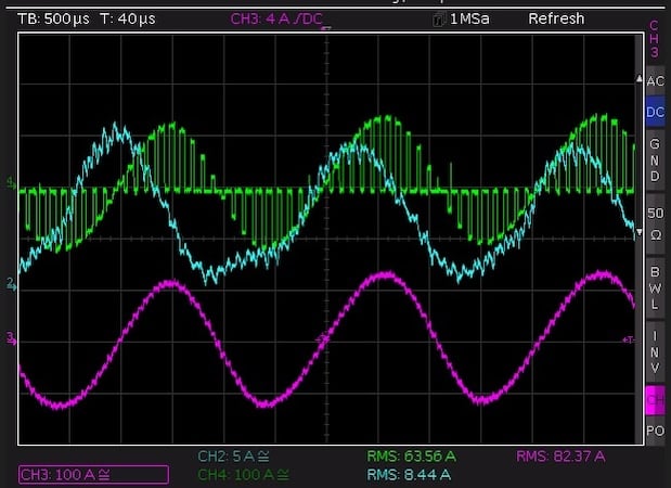
Figure 5. Measurements on an IFX HP-Drive module with a TDK film capacitor. Image used courtesy of Mankel-Engineering.de and Bodo’s Power Systems [PDF]
Example:
➔ ICrms = 1.3 * 250A * 0.5 = 1.3 * 125A = 162,5A
With these rough calculated capacitor ripple current, you can check in the capacitors data sheet (Figure 4), and determine which one may fit to your design to cover this value.
Figure 5 shows an example of a PWM inverter currents measurement.
The currents of CH2 and CH4 were each measured with a Rogowski coil and the measurement at CH3 with an active AC/DC current clamp.
CH2 shows the current drawn from the DC supply, in this case, the battery. The current amplitude has the frequency of the output frequency with a superimposed current ripple of the switching frequency. The current ripple depends on the DC link capacitance and the leakage inductance of the supply line.
CH3 shows the phase current with the ripple of the pulse width modulation. The current ripple mainly depends on the load inductance.
CH4 shows the current drawn by the pulse width modulation from the DC link capacitor in a half-bridge. The current is driven into the load inductance by the pulse width modulation of the semiconductor switches and the envelope of the output current.
In this case, when a special capacitor for the HP-Drive module is used, only the current per half bridge can be measured due to the capacitor's specific connection conditions.
Capacitor - Ripple Voltage Vr
Explanation of used values in formulas - (Figure 6 (simplified) and 7).

Figure 6. Simplified DC-link voltage switching ripple (Vr). Image used courtesy of Rambow-Technology and Bodo’s Power Systems [PDF]
Rated Voltage (DC-Voltage) VR =VDC Maximum Ripple Voltage Vripple = Vr = Vpp = Vpkpk

Figure 7. DC-link voltage switching ripple (Vr) - modified curve, results (blue trace) and calculated peak-to-peak Envelope (red trace) over time; m = 0.50. Image used courtesy and Curve modified by Rambow Technology and Bodo’s Power Systems [PDF]
\[V_{Crms}=V_{pk}\times\frac{1}{\sqrt{2}}=V_{pk}\times0.7071\]
Formula 3: Simplified calculation of the Capacitor ripple voltage
For example, if the OEM or Tier1 specifies the ripple voltage (Vr) as +-12V, the peak voltage (Vpk) of the waveform is 12 V, but the ripple voltage is 24V.
VCrms = Vpk * 0.7071 = 12V x 0.7071 = 8.48 V
Capacitor - Capacitance
Calculating the capacitance C stands for the frequency in Hertz (Hz) and the period duration in seconds (s).
\[f=\frac{1}{\tau}\,\,\,\,\,\,\,\,\,\,\,\,\,\,\omega=2\,*\,\pi\,*\,f\]
Rearranging equations:
\[C*2*\pi*f=\frac{I_{Crms}}{V_{ripple}}\]
\[\frac{1}{2*\pi*f*C}=\frac{V_{ripple}}{I_{Crms}}\]
Equation:
\[C=\frac{I_{Crms}}{2*\pi*f*V_{rippel}}\text{uF}\]
Formula 4: Calculate capacitance value - expected to be most realistic!
Example:
VR or VDC = 400V
f=10kHz (10000Hz)
ICrms = 180A
Vpeak-peak = Vripple = 8V
DC=m=0.5
Capacitance can be approximated by:
\[C=\frac{I_{Crms}}{2*\pi*f*V_{ripple}}=\frac{180}{2*3.14*10*1000*8}=\text{358uF}\]
Power Dissipation
A DCLink capacitor will experience internal heating, which will increase as the frequency of the ripple current of the semiconductors increases. Based on the above sample calculating the power capacitor losses with low ESR - e.g. ~0.5mOhm:
PC = I2Crms * RCESR
Formula 5: Capacitor Power Dissipation
PC=180²A * 0.5mOhm = 32400 * 0.0005 = 16.2W
The following capacitance values for a 100kW inverter are based on best practice expertise:
650uF for 450V systems ➔ Capacitor 650uF/500Vr
400uF for 800V systems ➔ Capacitor 400uF/855Vr
Do not forget—capacitors' total heating and temperature rises depend on the following main factors:
- Self-heating
- DC-current on the bus-bars
- Heat Injection from the semiconductors (tabs)
- Cooling
- Time
Measuring the Results
Now, you have calculated the needed capacitor values provisionally to choose the capacitor, but you are not finished. Measuring and evaluating your results in a final hardware environment of the device will validate your results, and looking at the following issues will help you prevent unexpected thermal damages. More capacitance will not decrease the ripple voltage.
Looking at Figure 8, adding more capacitance than needed will not reduce the ripple voltage effectively. The allowable ripple voltage of ~12V will be achieved with ~350 uF. A capacitance value between 500 uF and 650 uF seems to be a good solution for handling the capacitor’s ripple current. Spending more would not be cost-effective.
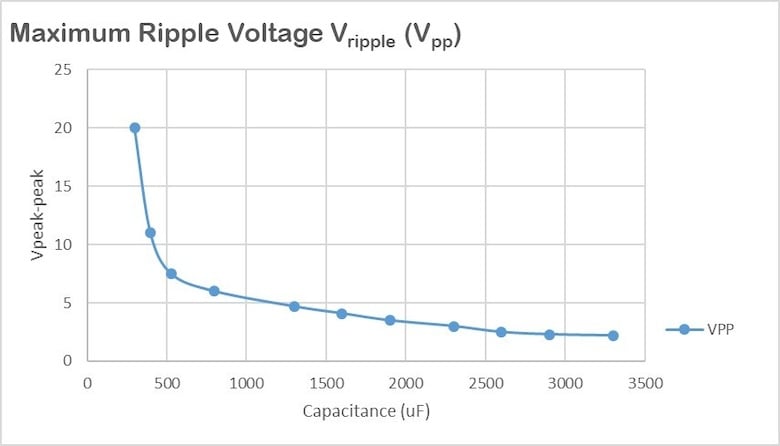
Figure 8. Example - Capacitance values versus ripple voltage. Image used courtesy of Rambow Technology and Bodo’s Power Systems [PDF]
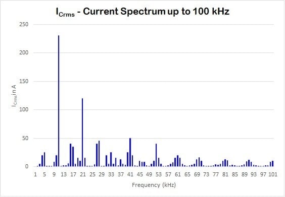
Figure 9. Amplitude of ICrms gaining losses up to 100 kHz. Image used courtesy of Rambow Technology and Bodo’s Power Systems [PDF]
Resonance and Capacitor Losses
Resonance between the capacitor and your switching circuitry leads to a wide frequency spectrum. Usually, people like to stop measuring at 100 kHz for a 10 kHz inverter – such results are indicated in Figure 9, which are seemingly good. However, you may be surprised when the capacitor fails “unexpectedly” due to temperature problems. The chart shows an analysis that does not represent the performance of a well-designed inverter.
Consider an extremely wide Frequency spectrum up to the MHz range (Figure 10).
With high-speed IGBTs and even more with SiC wide bandgap semiconductors, the switching frequency rises to 20 kHz and even more. On top, we have the inherently higher di/dt and dV/dt of these components compared with classical IGBT dedicated to motor control applications. Major losses are produced by the semiconductor switching current relay on influence above 100 kHz. Consequently, it does not make any sense to consider an operation bandwidth only up to 100 kHz. At a minimum, it should cover all the harmonics from the PWM with a magnitude higher than 10% of the total Irms (e.g., 300 kHz or even up to the MHz range).
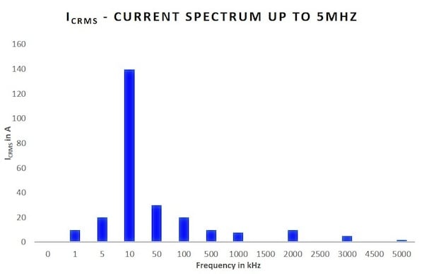
Figure 10. Amplitude of ICrms gaining losses up to 5 MHz. Image used courtesy of Rambow Technology and Bodo’s Power Systems [PDF]
What is critical here?
Example - looking at the ESR of a power film capacitor and how its losses (ESR) change over frequency:
ESR @10kHz ~ 1 x ESR according the datasheet
ESR@50kHz ~ 2 x ESR@10kHz
ESR@50kHz to 100kHz ~ 4 x ESR@10kHz
ESR@100Khz to 300kHz ~ 6 x ESR@10kHz
The truth is that with the above-mentioned ratios, the power losses of the DCLink capacitor will increase drastically. Remember:
PC = I2Crms * RCESR
Capacitors' ESR should be low within the entire relevant current spectrum bandwidth.
With some design efforts, the Capacitor manufacturer and you can reduce these effects drastically.
Nevertheless, there are still some other considerations:
- Even if you are experienced, estimating the complete spectrum in advance is not easy.
- All the harmonics shown depend on the pulse width modulation strategy and parameters you set.
- DC-link capacitors in automotive inverters are strongly affected by the switching semiconductors and their transients, plus possible ringing effects with high-order harmonics that are difficult to predict.
Selecting a suitable capacitor is physically possible with classic electrotechnical approaches and requires a precise model of the parasitic of a power stage built with this capacitor. That is a difficult task by nature. However, experience and best practice results can significantly help to shorten design iterations.
This article originally appeared in Bodo’s Power Systems [PDF] magazine and is co-authored by Dipl. Ing. Wolfgang Rambow, Rambow-Technology, and Katharina Mankel, R&D at Mankel-engineering.de.
Featured image used courtesy of Adobe Stock