Facebook
 Google
 GitHub
 Linkedin
Parameters of Current-Sensing Resistors
This article features Susumu parts that will detail the favorable construction of a reliable shunt resistor through the KRL current sensing resistor series.
In order to measure the current in an electric circuit, precisely kept low-resistance current sensing chip resistors should be used and the voltage drop measured over the component.
The required characteristics are tight initial tolerance, small TCR, high nominal power, and small size. There are, however, other important factors, like the effect of self-heating, the material of the resistive element, and on high frequencies, the equivalent series inductance (ESL) to take into account. In this article, we will discuss these factors and their role to be able to make a precise current measurement with Susumu’s unique KRL series of shunt resistors.

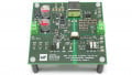
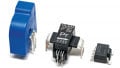
Figure 1. A sampling of Susumu's KRL current sensing series
Low resistance current sensing chip resistors were originally introduced as over-current protection devices in power supply circuits. Their application range has since extended, making these components important for power management of electronic devices and used to measure or adjust current. When an engineer wants to compare different current sensing resistors’ resistance stability over temperature, TCR alone would not give precise information about the measurement accuracy due to the fact that resistance is also influenced by the self-heating of the components. As there are more and more expectations towards electronics devices, the signal processing speed increases, generating a challenge for the designers to control noise caused by high frequency. In these cases, the self-inductance of the resistor has a crucial effect on the behavior of the shunt.
This article will detail the favorable construction of a reliable shunt resistor through the KRL current sensing resistor series of Susumu. This series is very popular due to its high power capability and low inductance at a lower resistive range, which helps control the noise of high frequency and high-speed applications of electronics devices as well as improves power dissipation capabilities due to the inverted construction and the long side terminals. Thus, these are suitable for current measurement in household appliances or automotive applications meeting the requirements of the standard AEC-Q200 up to the largest component package size.
The first thing to take into consideration when designing a component into an application is the datasheet provided by the manufacturer. It is recommended, however, to validate the included data in real application or laboratory conditions. In case of chip resistors — besides the usual parameters like the resistance, the nominal power and the initial tolerance of resistance at room temperature — the TCR (Temperature Coefficient of Resistance) as an indication of how the resistance changes with the temperature should be also considered.
For example, a part specifying ±100 ppm may have a resistance deviation from the nominal value of 0.01% per degree Celsius (or Kelvin) temperature change. At a temperature difference of 100 K, which is quite common in outdoor or automotive applications, this adds up a deviation accordingly of 1%. In most cases, the TCR information refers to the ambient temperature surrounding the component in the planned application.
Self-heating of Current Sensing Resistors
Current sensing (shunt) resistors are subject to power loss calculated by P = I2R (derived from Ohm’s Law). Therefore, to keep the dissipated heat low in order to avoid self-heating and its effect of the resistance itself, the device manufacturers offer the range of available resistance values down to the milli- and microohm region.
However, in order to cope with the ever-increasing currents to be measured, they must also adapt the performance specifications of the components. This is done using various technologies, such as in the construction as multi-layer resistance, with foil or curved solid metal as a resistance element.
Depending on the technological and material-specific possibilities, these resistors are specified differently. The maximum nominal power of a component is usually determined by its thermal limitations. For this purpose, the temperature is measured, for example, at the top of the chip and/or at its contacts. When the limit temperature is reached, a derating in the power dissipation capabilities starts. The maximum power loss for which a given resistance value can be kept therefore heavily depends on the heat dissipation ability of the components. To avoid power derating, the manufacturers strive to avoid so-called hotspots in the design of resistors.
TCR and PCR
When comparing different current measuring resistors, the TCR alone would not give sufficient information about the expected accuracy over the operating temperature range, because the resistance would not only change with the ambient temperature but also due to self-heating. Thus, another parameter comes into play: the PCR (Power Coefficient of Resistance). An inferior in terms of TCR device can deliver more accurate reading than its competitor due to the PCR effect if its self-heating is significantly lower.
Self-heating Resistance Example
Assume that the resistance of type B would show more accurate results due to its narrower TCR. Assuming R = 100 mΩ for both types, the self-heating, depending on the structure or technology used, shows very much different values. In this example, the type B with a TCR of ± 40 ppm is heated by 100 K, while the metal foil resistor of the KRL series with TCR of ± 50 ppm would only warm up by 60 K.
The self-heating resistance is calculated according to:
R = R0 TCR ΔT
100.4 mΩ for the type B respectively
100.3 mΩ for the type KRL
One can see from this calculation example that due to lower self-heating the KRL series current sensing resistor — despite its larger temperature coefficient — provides the more accurate measurement result.
Power Derating
The power rating of the resistor shows what the maximum energy that the resistor is able to dissipate without being damaged or degraded.
Most of the manufacturers indicate their power rating at 70°C in free airflow. Above this temperature, there is degradation due to stress on the material. The temperature where the power dissipation must be derated to 0 is also indicated. This is the maximum possible storage temperature of the resistor.

Figure 2. Indicating power rating at 70°C
In the case of Susumu's KRL series, depending on the constantan or manganin alloy used as the material of the resistive element, the power derating curve shows a higher derating point. This is due to the unique construction of the component and is usually the reason that the KRL series could be used on higher-rated power or on the same rated power in smaller case size compared to many other parts.

Figure 3. Curve shows higher derating point
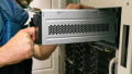
Current Measurement in Practice
This reliable method of measuring currents can be found in automotive applications but also established for example in home appliance technology. One can find such current sensing resistors in vehicles, either in the trunk lid control or seat adjustment; also valve regulators or brake systems require precise current measurement. A manufacturer of cleaning robots, such as those used in residential places, was able to solve three problems at once using the KRL resistors. The DC / DC converter of the robot’s power supply requires a 10 mΩ shunt, which is specified for a power loss of at least 2 W, as current above 10 A should be measured, and the controller requires an input voltage of at least 100 mV. Usually, for 2W heat dissipation, a shunt with 2512 size is required, but due to limited space, it does not fit. By choosing resistor with soldering terminals on its long sides (long-side terminal KRL), a smaller 2010 case size is enough, as on wider solders, the heat is conducted easier and faster towards the PCB.
Resistive Element Material
As current sensing is based on voltage measurement on a precise stable resistance, all factors that may have an influence of this voltage need to be considered. Above, we detailed the TCR’s and the PCR’s influence, but there is a further effect that may lead to measurement mistakes. As the resistor consists of different metal materials connected together, the so-called thermocouple effect (Seebeck effect) may also distort our measurement. When different metals are connected together at one point, and this intermetallic junction is subjected to heat, a small (microvolt magnitude) voltage may arise between the free ends, that leads to further distortion of the precise measurement. Constantan-based resistive elements have higher thermo-EMF, while the manganin-based versions are considered to be low thermal EMF sources and are therefore more stabile for precise applications.
Equivalent Series Inductance
There is an important factor to take into account when making precise current sensing on high frequencies, the equivalent series inductance (ESL) of the resistor, that should be kept as low as possible. A number of electronic devices require precise power management that could be provided by using DC/DC converters. These switching devices operate on several hundred kHz frequencies. If the ESL of the current sensing resistor is large, the transition switching pulses contain noise, that affects the accuracy of the control, as the inductive impedance is proportional to the frequency and the inductivity: Z ~ 2pfL However, if ESL is small, such noise will become insignificant.
The inductance of conductor (non-coil) is provided by the following equation:
L=0.002 h(2.303log104h/d-1+μ/4)
Where h=conductor length, d=conductor width, and μ=permeability.
The inductance increases with the permeability of the material and length of the conductor and decreases with the width of the conductor. Therefore, when the material is fixed, low ESL can be obtained by shortening the conductor length and widening the conductor width. Susumu’s long-side terminal type resistor realizes low ESL with a shorter length and wider width of the resistive element by using its longer side as the terminal.

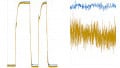
Figure 4. The shape of the waves using a short-side terminal resistor with the switching noise

Figure 5. The same waves when using a long-side terminal resistor, demonstrating a clear reduction of the switching noise
Using such low ESL current sensing resistors, the designer can avoid the need for using additional noise reduction circuits.
Long Side Terminals: Better Heat Performance and Noise Reduction
Susumu’s long-side terminal low resistance chip resistors were developed to increase heat dissipation. Due to this high power capability, these chip resistors have been very popular. In addition, new demand has arisen for high-frequency applications, where the low ESL of the long side terminal versions also provided significant advantages. Noise suppression in combination with low parasitic inductive influences indicates the accuracy increases significantly.
In the charge controller of electrical devices, near the battery, thermal properties play an important role as the electronics and battery heat up during charging and discharging. Due to the inverted structure (carrier ceramic above, resistive element below) in the resistor, no hotspots are formed, allowing rapid cooling, which reduces the influence of TCR/PCR on the measurement result.
Susumu's KRL Resistor Series
The KRL resistor series of Susumu is designed for high nominal power with low nominal resistances making them useful in current measurement. The structure with metal foil, which is attached to the underside of a carrier ceramic, promotes the uniform cooling of the component.
Further characteristics of the KRL series are low noise, low parasitic inductances, low thermal EMF, which could falsify the measurement result, low dead weight and their robustness. The latter is due to the inverse structure - with the metal foil under the carrier ceramic. The organic adhesive layer absorbs mechanical stresses due to the different length expansion of ceramic and printed circuit board material. The components can thus clearly exceed the requirements of the automotive standard AEC-Q200 up to the largest case sizes.
The KRL series is available in different layouts: with rated resistances from 1 mΩ to 1 Ω, in sizes of 0603 to 4320, in rated power classes from 0.25 to 10 W, as standard with a TCR of 50 ppm, with initial resistance tolerances of ± 1% and with short-side, long-side, 4K, and gold terminals.
About the Authors
Tobias Jung is a Certified Technical Specialist at IHK. HE currently work as the Senior Product Manager for Passive Components at Endrich Group since November 2016.
Zoltán Kiss holds a Ph.D. and Master's Degree in Electrical and Electronics Engineering at Budapest University of Technology and Economics. He is skilled in Electronic component sales and design-in, Educating colleagues, Technical writing, Presentation, Retail, Sales Management, Graphic Design, and Software Design. He currently works as the Export Manager, responsible for international sales at Endrich Group.
This article originally appeared in the Bodo’s Power Systems magazine.
Related Content