Facebook
 Google
 GitHub
 Linkedin
nHPD2 Power Modules Where Innovation Meets Requirements
This article highlights Hitachi Europe, Ltd. introduction of nHPD2 Power Modules as the first high-voltage IGBT-based power module for traction, etc..
More than two decades ago, the first high-voltage IGBT-based power module was introduced. Today, it's an industry standard used for traction, motor drives, and renewable energy applications. With increased requirements regarding temperatures, switching frequencies, and higher power density—combined with reduced system costs and enhanced reliability—arise a new solution.
Hitachi introduced a new industrial standard package and named it nHPD2. The nHPD2 package implies an evolution for medium voltage power converter design.
Lowest stray inductances enable optimized performance for both SiC and Hitachi’s Side Wall Gate IGBTs, allowing the market to choose the best solution for their particular design challenge and set up in the range of 1700V up to 6.5kV.
The nHPD2 Package
The nHPD2 Series provides high function, half-bridge power modules, and incorporates temperature sensors and current sense terminals for optimum design performance.
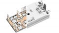
The series offers a dual package outline for the full range of voltage and current ratings with the same footprint; different heights to align with the transition from the established heights set by the former IHM standard, allowing for a common mechanical design and high level of design re-use for converters with different ratings. The compact form factor, high power density facilitates and robust construction enable the designer to realize industry-leading converter designs.

Figure 1. nHPD2 Series Low (left) and High Voltage Package
Product Line-up
The nHPD2 Series product line up covers from 1700V up to 6500V rated modules with current ratings up to 1200A. All products in LV package are available now as samples or in mass production. These include:
- 1700V, 900A SiC – MBM900FS17AL
- 1700V, 1000A Si – MBM1000FS17G
- 1700V, 1200A Si – MBM1200GS17G2
- 3300V, 450A Si – MBM450FS33F
- 3300V, 600A SiC – MSM600FS33AL
- 3300V, 800A SiC – MSM800FS33AL

Figure 2. World’s highest power density with nHPD2 3.3kV/800A without SBR diode
The target portfolio for the HV package, which begins its rollout in the first half of 2019, is shown in Table 1.
Voltage |
Current |
Chip |
3300V |
600A |
Si |
3300V |
600A |
SiC |
3300V |
800A |
SiC |
4500V |
450A |
Si |
4500V |
600A |
SiC |
6500V |
300A |
Si |
6500V |
450A |
SiC |
Table 1. HV Target Portfolio
Latest Technology
Hitachi continues to apply the latest technology breakthroughs to the nHPD2 series to continue extending the performance envelope. The application of latest generation side gate IGBT, SiC, on board temperature sensing and Copper sintering for improved die attach ensure the best output power, energy losses, control and lifetime.
Low loss, High Controllability: The Motor System Cost Merit
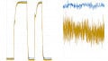
The Side Gate IGBT reduces energy losses and improves controllability compared to conventional trench IGBT. The loss trade-OFF can be improved with up to 35% reduction in turn OFF energy or 15% reduction in saturation voltage as shown in Figure 3a. Low gate charge reduces the load on the gate driver and low reverse recovery dv/dt and voltage overshoot allow optimization of the turnon to lower switching losses further and enable easy integration into a converter as shown in Figure 3b.

Figure 3. Side Gate IGBT performance. Vce – Eff tradeoff (left); Eon+Err –recovery dV/dt- motor costs (right)
Moreover, shifting to an application level cost benefit, two options may be considered. In place of a full focus on reducing system electrical efficiency (Eon+Err), there is an opportunity to trade-OFF the full benefit to reducing the cost of the motor or generator. Since the motor and dv/dt filter cost can be linked to the level of isolation provided, by relaxing the turn-OFF and recovery loss performance, the switching dv/dt (kV/us) can be reduced allowing the motor specification to be relaxed and cost down to be enjoyed.
For example, an existing design based on a motor with an isolation 7kV/us, by accepting the status-quo Eon+Err efficiency, the motor isolation may be downgraded to 2kV/us. Surveying common motor suppliers, we can translate this to a shift down from a motor with reinforced winding isolation to a motor with standard isolation regarding IEC/TS 60034-17. Cost merit is a factor of 2.5 which correspondents to a cost saving of 1.5k€ for a 30kW motor.
Further to motor cost saving potential, the market leading gate capacitance values (Qg) of side wall gate that offer significant reductions is the power required to drive the gate. A typical GDU rated for conventional IGBT half bridge modules rated 1400A/1700V may consume 2x10W of power per GDU. Adopting low Cres side wall gate requires only 2x5W. Translating to a monetary benefit, the cost down opportunity may be as much as 50% reduction for the GDU solution.
The reduced reverse transfer capacitance (Cres) of Side Gate IGBT leads to improved Short Circuit performance with better-controlled gate voltage and lower peak collector current. This provides a power module that is more robust under short circuit conditions and reduces the current that must be handled in the converter design.
Maximum Lifetime and Power Density
The application of Hitachi’s proprietary copper sintering to replace the solder layer between the IGBT chip and the substrate greatly increases the robustness of the module, in particular increasing the power cycle life by 10 times compared to standard solder. It also improves the thermal impedance of all dies and the I2t of the diodes and is providing the highest possible power density.
This is particularly suited to high-performance traction and wind power designs requiring aggressive acceleration and highly dynamic mission profiles, whilst ensuring total reliability throughout the lifetime of the system. Figure 4 shows the copper nanoparticles sintered to form a strong die attach joint.

Figure 4. Copper sintering die attach process
Figure 5 shows the cross-sectional image after power cycling of more than 400k cycles with Δj=125K and Tjmax=175°C, setting a new durability benchmark in a market used to lesser goals, like ΔTj=<100K and Tjmax=150°C.

Figure 5. Cross section after power cycling
Next-Generation Silicon IGBT
The nHPD2 is also optimized for the next generation of Hitachi’s Silicon IGBT called Dual Side Gate. It is Hitachi’s main strategy to offer best in class performance of Silicon IGBT and SiC MOSFET in the nHPD2 package to make our customer systems flexible and successful. The dual side gate IGBT breaks through the conventional performance limitation of silicon. By applying dynamic carrier control, the turn OFF loss can be reduced by 45% compared to conventional trench IGBTs and the Eoff – Vce(sat) tradeoff approaches that of SiC MOSFETs but using standard silicon processes. To break though the limitation on IGBT loss reduction, techniques for controlling carrier concentration right before turn-OFF switching have been found to be highly effective.
Figure 6 shows the simulated stored carrier density distribution and performance of VCEsat and Eoff on a cutting-edge side gate HiGT for high and low hole injection structures.

Figure 6. Simulated carrier distribution of hole for leading-edge side gate IGBT
Tuning the p-collector dose concentration enables controllability of conductivity modulation in the drift layer. However, the carrier density near the emitter surface cannot be controlled effectively due to injected carrier from the accumulation layer of the MOS gate. This accumulated carrier leads to large turn-OFF current during turn OFF switching and then limits the IGBT Eoff from being reduced further. As the method of breaking though such a limitation, we consider the ideal stored carrier profile, shown in Figure 7.

Figure 7. Carrier distribution with low density for low-loss performance
In the conduction state of the IGBT, a large amount of carriers should be stored for low VCEsat, while right before turn-OFF switching, the stored carrier concentration near the emitter surface region of the drift layer should be reduced to promote depletion of the drift layer, reducing the turn-OFF current for low Eoff. By applying this idea, Eoff is lowered while maintaining low VCEsat, thus breaking though the conventional limitation of an IGBT: conduction versus switching loss trade-off performance.
Figure 8 shows a schematic cross-sectional view of the dual sidegate HiGT structure.

Figure 8. Concept and structure of proposed novel dual side gate IGBT
Driving the two independent gates enables effective controllability of conductivity modulation. In conductive mode, both side gates act to inject a large number of electrons, thereby reducing VCE(sat).
In advance of a switching event, one of the two side gates are turned OFF while the other gate remains in the on-state to reduce the amount of stored carriers, thereby enabling faster switching during the final turn off. Aside of the key dual gate channel feature, the merits of the standard side wall gate structure equally apply. This means low Miller capacitance, easy drive and reduced short circuit peak currents, each of which contribute to enhanced device and system durability.
Simulating the dual side-gate HiGT, Figure 9 shows the simulated stored carrier distribution in the conductive mode (VGsE/ VGcE = +15 V/+15 V) and switching mode (VGsE/VGcE = +15 V/-15 V).

Figure 9. Simulated stored carrier distribution for dual side gate IGBT
In the conductive mode, electrons are injected from both gates and the stored carrier concentration near the emitter region is increased by the generated conductivity modulation effect.
On the other hand, stored carrier density at the surface emitter region is decreased by oneside gate turn-OFF control. Figure 10 shows the simulated output characteristics of the dual side gate HiGT.

Figure 10. Simulated output characteristic on dual side gate IGBT
After trial fabrication, the dual side gate solution in conductive mode, realized less than 2.7V VCE(sat), showing a 6.0% reduction compared to the best in class MBN1800F33F trench gate (2.85V @ Tj=150°C), despite conduction loss being the secondary performance target, with switching loss reduction the primary goal.
Next, turn-OFF switching characteristics of the dual side-gate HiGT were simulated. Figure 11 shows the applied gate input signals and the obtained turn-OFF waveforms the timing delays for Gs and Gc signals (tdelay).

Figure 11. Turn-OFF drive signal and simulated turn-OFF waveform of dual side gate IGBT
As tdelay increased, a higher speed turn-off waveform is obtained. This is the direct effect of reducing the stored carrier concentration using Gc control and tdelay right before the turn off signal of Gs.
Table 2 summarizes the simulated stored carrier profiles after the elapsed t delay i.e. after Gc negative gate bias (-15V) is applied. It also highlights the effect on conduction loss during tdelay (Econd), turn-off switching loss (Esw) and total Eoff (Econd+Esw).
As tdelay increases, a decrease of stored carrier concentration and an increase of Econd is observed, whilst showing a dramatic reduction of Esw. Thus, the proposed dual side-gate HiGT had 31% lower Eoff than the conventional single side gate HiGT with a 40μs tdelay drive profile.

Table 2: Simulated Eoff dependency on tdelay
Next-Generation SiC “TED-MOS”
Hitachi also brings SiC MOSFETs to industrial applications to further drive efficiency improvements in the nHPD2 package. Hitachi’s proprietary next trench SiC MOSFET technology, the “TED-MOS”, uses a special trench etched double diffused structure to offer leading performance with low energy losses and improved short circuit durability over standard DMOS and trench MOS.
The structure of TED-MOS ensures a robust and reliable chip that is easy to control. Both Drain-Source resistance and switching losses are reduced compared to SiC DMOS and trench structures.

Figure 12. Hitachi SiC TEDMOS performance compared to conventional SiC DMOS. Left: Lower on-state resistance. Center: Lower switching loss. Right: Improved circuit durability
Electric field around the trench
Most notable is the electric field around the trench, reduced compared to conventional trench structures to give a more reliable chip. Short circuit current is also better controlled, resulting in a short circuit durability that is similar to standard silicon IGBTs at ≥10μs. This performance withstand capability is setting new standards in the SiC market, especially when compared to the more modest value of 3-5μs for most existing SiC products in the market today.
Combination of TED-MOS 10μs short circuit capability and nHPD2’s current sense auxiliary terminal
Rather than shifting from standard proven detection and reaction methodologies developed over the past 20 years of silicon device use, the combination of TED-MOS 10μs short circuit capability and nHPD2’s current sense auxiliary terminal offers to match silicon performance we have become accustomed to. Intensive engineering effort anticipated to overcome the need to turn off a short circuit within 3μs for SiC devices is no longer a requirement by adopting Hitachi TED-MOS.
Modularity and Scalability
The nHPD2 module allows easy paralleling and optimized realization of multi-level topologies regarding stray inductances and system costs.

Figure 13. nHPD2 bus bar arrangement on heat sink for 3 levels

Figure 14. Example for a compact and compatible inverter configuration
Development of modern and flexible converters
Hitachi is supporting the development of modern and flexible converters by applying innovation and advanced technology to a range of industrial focused power modules. The modules are well suited to high-performance applications that demand the highest levels of efficiency, lifetime and power output.
The common module outline for the nHPD2 series facilitates a high level of design re-use and common design across converter power ranges to suit a wide range of applications.
Hitachi’s focus
Hitachi’s focus on bringing the best performance to the market through innovation and advanced technology is evident in the future roadmap for the nHPD2 series. The latest generation Silicon IGBTs and SiC MOSFETs line-up already available now will be followed by further advanced Silicon and enhanced SiC MOSFET generations to continually push the boundaries for higher efficiency, better performance and flexibility for the next decades.
The integration of copper sintering for SiC MOSFET and side gate IGBT will be the next big step to secure the success of our customer. Furthermore, Hitachi is offering lifetime simulations based on customer mission profiles and dedicated measurements in our high-tech lab in Maidenhead, UK related to user's requirements.
About the Author
Michael Sleven works in business development for Hitachi Europe, Ltd. He has worked in the electronics sphere for 20 years at companies including Infineon, Mitsubishi Electric Europe, REFU Electronik GmbH, and Bosch.
Related Content