Facebook
 Google
 GitHub
 Linkedin
Leading-Edge Power Modules for the New Era in Traction Converters
This article highlights Infineon Power Modules development for traction applications particularly in energy-efficiency and emission-free transportation systems.
Today, 55 percent of the world’s population live in urban areas, a proportion that is expected to increase to 68 percent by 2050 [1]. With this ever-increasing urban population, in combination with an increasing number of commuters on public transport, and a growing awareness of energy-efficiency and emission-free transportation systems, traction application is back in the limelight.
A megatrend like urbanization provides a tailwind to improve, enhance and innovate today’s traction converters and components within its ecosystem. Power semiconductors, which are core components of traction converters enhancing their reliability, efficiency and longevity, are of utmost importance.
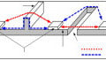
Since the early 1990s, Infineon has been setting trends in developing leading-edge power semiconductor modules and technologies to facilitate innovation in converter design. Product offerings address the full spectrum of traction applications, from propulsion converters to auxiliary converters, enabling designers to achieve their design targets. Typical topologies for traction sub-applications such as trams, metros, electrical multiple units (EMU), high-speed trains and locomotives, are shown in figure 1a and 1b.


Figure 1: Schematic depiction a typical topology in EMUs, high-speed trains & locomotives (above) and a typical topology in trams and metro applications (below)
FZ1500R33HE3 in IHV-B
FZ1500R33HE3 in IHV-B 140 mm x 190 mm housing has been the basic building block in propulsion converters for applications with 1500 VDC – 2200 VDC links, i.e., metros, EMUs, high-speed trains and locomotives. 1500 A has been the preferred and most commonly available current rating; Infineon raises the bar once again with the introduction of the first 2000 A/3300 V in IHV-B package.

Figure 2: Increasing nominal current in IHV modules for facilitating inverter design for traction applications
Boosting power density, with the first 2000 A/3300 V in IHV-B package
Power density matters. The new 2000 A/3300 V module, the FZ2000R33HE4, offers a massive increase of 33 percent current density in comparison to the state-of-the-art 1500 A/ 3300 V module, raising the current density in IHV-B package to 7.52 A/cm2. Applications such as metros, EMUs, and high-speed trains are based on today’s well-established IHV modules due to its reliability, robustness, longevity and a field-proven record of accomplishment.
Infineon FZ2000R33HE4 Module
Infineon introduced the FZ2000R33HE4 with the IGBT4 and EC4 diode in the 140 mm x 190 mm IHV-B housing to support traction converter designer can enhance existing converter platforms with a minimal design effort. Customers can easily design-in the 2000 A module without changing the DC-link and heatsink designs. A new cell structure of the IGBT4 in the FZ2000R33HE4 enables a gate charge of 40 μC, lower than the 1500 A device. This ensures that the gate driver design needs only a minor adaptation.
Many of the existing traction designs use two modules of 1000 A in parallel, which can be replaced with one 2000 A module reducing the overall volume of the power stack. Additionally, the new 2000 A module can easily address new metro platforms with renewed motor designs requiring higher peak current, as well as EMUs and locomotives operating in high gradient areas.
Infineon FZ1400R33HE4 Module
Infineon introduces another new module in the IHV-B package, the FZ1400R33HE4 in a 140 mm x 130 mm footprint increasing the current density to 7.69 A/cm2. The 1400 A module in a 140 mm x 130 mm footprint enables customers to further optimize their existing converter designs and further improve the cost-performance ratio.
Increasing the current density of power modules leads to higher temperature ripple under cyclic load conditions, resulting in reduced lifetime. Enhanced aluminum wire-bonding technology is implemented in both new modules to increase the power cycling by a factor 2 times the standard bonding technology. The increased power-cycling factor can be further utilized to increase RMS current in applications with cyclic loads.
XHP™ – flexible high-power platform for compact and scalable inverter designs
Enhancing the IHV-B package satisfies the needs of today’s traction converter. But, what about the requirements for a new, improved and standardized power semiconductor module which major European suppliers of traction equipment have outlined [2]? Infineon’s fleXible High-power Platform (XHP™) addresses exactly this requirement.
The key motivation for introducing the XHP™ platform was to address system requirements for higher flexibility, higher current density and higher efficiency. Additionally, for clean switching, higher robustness and reliability, with a reduction of system costs.
XHP™ Module Family
Within the XHP™ module family, the XHP™ 2 package is designed for voltage classes of 1.2 kV, 1.7 kV up to 3.3 kV, whereas the XHP™ 3 package is meant for voltage classes from 3.3 kV up to 6.5 kV. Both packages have the same footprint of 140 mm in length and 100 mm in width to facilitate the use of a common heatsink profile and homogenous converter platforms.
Sharing the same height of 40 mm for both module types ensures that standard insulators and mechanical spacers can be used. Developing both module solutions with identical dimensions supports designers’ preferences for building a homogenous converter platform covering different voltage classes and power ranges. A single module becomes a building block for a converter, and higher current requirements can be fulfilled by simply building one block next to the other.
XHP™ 3 – The high voltage module
For the voltage classes of 3.3 kV and 6.5 kV, the XHP™ 3 module has been developed in a half-bridge configuration with an isolation voltage of up to 10.4 kV. The power terminal arrangement is further simplified with the DC terminals on one side and the AC terminal on the other side of the module. Due to the power terminal arrangement, the laminated DC-link busbar design is simplified, and thus, a low-inductive converter design is feasible.
Auxiliary terminals are arranged in the area between the power terminals, this area been assigned for mounting gate driver electronics. The XHP™ 3 provides a large space of approximately 80 mm x 99 mm to mount the gate driver hardware, with or without an adapter board.
XHP™ 3 and XHP™ 2 Comparison
A structural comparison between two conventional IHV-B modules in half-bridge configuration and four XHP™ 3 modules results in a reduction of total commutation inductance from 90 nH down to 15nH. This enables faster switching and lower overvoltage to achieve a reduction in switching losses. In comparison to an IHV-B, the XHP™ 3 offers easy gate driver assembly and accessibility, along with higher clearance and creepage distances.

Figure 3: A step forward in flexibility: Infineon’s high-power platform for higher power density and efficiency – XHP™ 3 (left) and XHP™ 2 (right)
The system’s stray inductance of a converter based on XHP™ 3 typically ranges from 30 nH to 40 nH, but even at similar system stray inductance, the XHP™ 3 switches faster than the IHV-B module reducing Eon losses by roughly 21 percent. Due to the lower stray inductance of XHP™ 3 and faster switching, it is important to experimentally select the gate resistor according to the application requirements.
Increasing the voltage slew rate dv/dt results in a higher turn-OFF di/dt, which in turn reduces the turn-ON losses but generates higher voltage overshoots. At a similar dv/dt and system stray inductance, the voltage overshoot for the XHP™ 3 is reduced by 30 percent, which in turn results in a 5 percent reduction of turn-OFF losses [3].


Figure 4: Switching behavior of XHP™ 3 compared to IHV-B, above: turn-ON, below: turn-OFF
Traction Applications
In traction applications, where 1500 V is a prevalent catenary, or where the intermediate circuit voltage ranges, for example, from 1800 V to 2200 V, it is customary to use 3300 kV switches in a standard 2-level topology. System complexity in 2-level converter designs can be significantly reduced by using XHP™ 3 modules, additionally providing the possibility to scale the power if required.
An XHP™3 package in 3.3 kV (FF450R33T3E3_B5) has an isolation of up to 10.4 kV which supports topologies like the 3-level chopper and the conventional 3-level NPC-1 topology as depicted in Figure 5, [5].

Figure 5: Schematic depiction of 3-level topologies in traction applications
However, it is not only about power density. Applications such as metros have higher cyclic loads, which demand higher power cycling. The new FF550XTR33T3E4 module with the IGBT4 and .XT technology in XHP™ 3 package addresses such applications, which require higher power density and longer lifetimes.
Enhancing lifetime and power density with FF550XTR33T3E4 IGBT4 and .XT technology
The new FF550XTR33T3E4 module in the XHP™ 3 package is embedded with the new IGBT4 and EC4 diode based on the field-proven trench gate structure, in combination with an enhanced edge termination. The forward voltage drop of the EC4 diode is 200 mV lower than the EC3. The combination of enlarged chip area and the .XT technology further improves the thermal resistance Rthjc by 20 percent. The .XT technology with enhanced aluminum bonding is implemented in this module to meet application requirements for higher power-cycling capability and higher power density.
The new chip technology, reduced thermal resistance, and an enhanced bonding technology forms the new 550 A/3300 V half-bridge module to deliver an increased rms current of 30 to 40 percent. Applications like metro and EMU demand longer lifetime under cyclic load condition in combination with higher power density for their next-generation converter platforms.
.XT technology: increased power-cycling capabilities
.XT interconnection technology was introduced in the PrimePACK™ module to increase power-cycling capability to address higher lifetime requirements for applications like wind, special industrial servo/high-performance drives and commercial vehicles. The .XT technology in 1200 V and 1700 V extends the power-cycling capabilities by a factor of 10. With the launch of the new FF550XTR33T3E4 module, the spectrum of .XT interconnection technology has been further expanded to include 3300 V modules to extend the power-cycling capabilities by a factor of 5.
Applications like metros, EMUs, high-speed trains and locomotives have DC-link voltages in the range of 1500 V to 2200 V, which can be addressed by 3.3 KV modules in the IHV-B and XHP™ 3 package. However, some of the metro lines and trams run on 750 VDCcatenary, which requires power semiconductors with 1700 V blocking voltage in a 2-level configuration. Infineon has introduced the new XHP™ 2 product platform equipped with the 1700 V IGBT5 .XT to meet the requirements of such applications.
XHP™ 2 – Smart solutions for propulsion converter in urban transportation systems
Megatrends like urbanization are driving investment in traction sub-applications such as trams and metros, which operate for short distances within the city limits. A typical tram stops after a few 100 meters, while a light rail or metro have a typical distance of 1000 m between two stops. Figure 6 depicts a generic exemplary mission profile for an electric propulsion system of a metro application.

Figure 6: Exemplary mission profile for a Metro application
During the acceleration phase, the energy in the converter is mainly conducted by the IGBTs, and during the braking phase, the freewheeling diodes (FWD) have to conduct the generated reverse energy. These short distances performed in day-to-day operation result in enormous electrical stress, especially on the power modules. IGBT and diode chips in the power modules have to withstand this enormous electrical, mechanical and, in particular, thermal cycling stress.
Major criteria for the long-term reliability of power devices depend upon the power modules’ capability to withstand these cyclic thermal loads. The dominant end-of-life (EOL) mechanism for standard joining technologies in such demanding applications are the degradation of solder layers and the aluminum-bond wire lift-off on the chip.
These interconnections are highly stressed by the relative temperature swing ∆T at the resulting junction operating temperature Tvj,op and by the duration of this thermal stress (ton) [4,5]. Based on these challenging application requirements, today’s power modules are typically dimensioned by selecting a higher current rated module or by paralleling smaller modules to reduce the thermal loads and fulfill the high lifetime requirement. To achieve optimized solutions in the power converter, the typical wear mechanisms must be significantly improved and shifted to a much longer running time, or if possible, eliminated.
Infineon’s 5th generation chip with its .XT technology
Infineon’s 5th generation chip with its .XT technology provides a considerable enhancement in terms of robustness against cycling loads [6]. In addition to the optimized chips and joining technologies, the ratio of chip sizes between IGBT and diode are balanced based on the application requirements. Figure 7 compares the results of a lifetime simulation of a metro mission profile. For addressing the requirement of 30 years of lifetime, two devices of 1200 A/1700 V IHM in parallel are required. In comparison, only one 1200 A/1700 V XHP™ 2 module with IGBT5 .XT is required.
Integrating the new 5th generation IGBT and diode technologies with operational junction temperature Tvj,op, of 175°C, the maximum module current for the 1700 V XHP™ 2 is further increased up to 1800 A. Infineon introduces two new modules in 1700 V XHP™ 2 housing, the FF1800XTR17T2P5 and the FF1200XTR17T2P5. They are equipped with 5th generation IGBT and emitter-controlled diode with .XT joining technology.
Improving power density and efficiency is not only limited to propulsion converters. There have also been significant improvements in weight, volume and efficiency in auxiliary traction converters by using SiC-MOSFET devices. Here, Infineon offers a wide range of CoolSiC™ MOSFET modules to facilitate the next generation of energy-efficient auxiliary converters.

Figure 7: Comparison of lifetime for XHP™ 2 against two IHM modules
SiC-MOSFET to boost system efficiency and power density in auxiliary converters
Auxiliary converters commonly known as Auxiliary Power Units (APU) are integrated into trains to isolate power lines to support electrical loads, e.g. fans, heaters, air conditioners, laptops, power sockets etc. Since weight and efficiency are the key requirements for APUs in-rail vehicles, the use of CoolSiC™ MOSFET modules show a huge benefit due to the unique performance of SiC. Compared to state-of-the-art Si solutions, CoolSiC™ MOSFET modules offer several advantages for the application including:
- Higher efficiency
- Smaller size of passive components like chokes, transformers, capacitors etc. due to operation at higher switching frequencies
- Less cooling effort to decrease weight and volume of the system• Less audible noise.

Figure 8: Inverter power depending on SiC MOSFET module
Infineon’s CoolSiC™ MOSFET Modules
Infineon’s CoolSiC™ MOSFET modules with an ON-state resistance RDS(on) of between 45 mΩ and 2 mΩ are a perfect match for APU applications. The dynamic performance of the SiC-MOSFET, being a unipolar device, is mainly determined by the capacitances, and thus optimized in terms of dynamic losses. The ratio of the gate-drain reverse capacitance Crss compared to the input capacity Ciss is designed to suppress parasitic turn-ON events. The knee voltage-free conduction behavior offers a significant potential for loss reduction.
Auxiliary Power Units (APU)
APU generally operates under partial load conditions, resulting in considerably lower conduction losses for a majority of the operation lifespan. Additionally, positive temperature coefficients of the ON-resistance makes the devices suitable for paralleling.
Package Design and System Layout
Electrical performance, however, is only part of the story. For fast switching of SiC devices, the package design as well as the system layout is of equal importance. For this reason, Infineon has developed a broad portfolio of packages. The popular and flexible Easy 1B / 2B as well as the 62 mm power modules are used to implement half-bridge configurations, booster solutions, H-bridges and six-packs.
The flexible pin grid of Easy modules makes the PCB layout easy and offers <10 nH stray inductance. This is a factor 5 improvement over previous solutions, and represents a valuable step in power module design. 62 mm modules provide increased clearance and creepage distances for the DC/DC converter, as well as the ISO voltage of 4 kV.
Summary
Infineon’s product offerings address the full spectrum of traction applications, from propulsion converters to auxiliary converters, enabling designers to achieve their design targets. The focus has been to continuously enhance the IHV-B product family to enable improvement of the existing converter platform.
The new 2000 A/3300 V with 33 percent higher current density addresses application requirements for more power. The 1400 A offers a better cost-performance ratio in comparison to the state-of-the-art module.
XHP™ 3 and XHP™ 2 have been developed in line with the requirement set by the European traction equipment manufacturers and will be the future building block of traction converters. The new 1800 A/1700 V in XHP™ 2 enables customers to achieve the required life-time, and to reduce the module size at the same time for applications such as trams and metro systems with 750 VDC link.
Infineon offers SiC-MOSFETs in the flexible Easy 1B and Easy 2B packages as well as in the field-proven, low-inductive 62-mm package. SiC-MOSFET modules provide higher system efficiency, reduce the number of passive components, and reduce the cooling efforts to decrease the weight and volume of the system.
Last but not least, they also significantly reduce the audible noise. From high-power, high-voltage propulsion converters to, low-voltage auxiliary converters, Infineon is the one-stop solution provider for reliable power semiconductors.
About the Author
Vishal Jadhav specializes in semiconductors and embedded systems. He currently works as the Technical Marketing Manager at Infineon Technologies since October 2016.
Wilhelm Rusche has worked as the Technical Marketing - High Power Innovation at Infineon since October 2014. He is responsible for the definition and specification of new products in power electronics. Rusche is a Graduate Engineer in Electrical Engineering at the Comprehensive University Paderborn Dept. FH Meschede.
Andre Lenze is the Technical Marketing Manager at Infineon in the Industrial Power Control division. There he oversees the CoolSiC Easy module product family. Lenze studied industrial engineering at the Fachhochschule Südwestfalen-Soest with a focus on electrical engineering, marketing, and sales.
References
- [1] 2018 Revision of the World Urbanization Prospects by UN
- [2] http://www.roll2rail.eu, D1.2 - New generation power semiconductor -Common specification for traction and market analysis, technology roadmap, and value cost prediction.
- [3] Buchholz S.; Wissen, M.; Schütze, T.; Electrical performance of a low inductive 3.3kV half bridge PCIM 2015; Nuremberg, Germany
- [4] A. Stegner, et al., Next generation 1700V IGBT and emitter controlled diode with .XT technology, PCIM, Nuremberg, Germany, 2014.
- [5] A. Ciliox, et al., New module generation for higher lifetime, PCIM, Nuremberg, Germany, 2010.
- [6] W. Rusche, et al., Lifetime Analysis of PrimePACK™ Modules with IGBT5 and .XT, Bodo ́s Power 01/2016
This article originally appeared in the Bodo’s Power Systems magazine.