Facebook
 Google
 GitHub
 Linkedin
Innovative Current Sensor without Toroidal Magnetic Core Offers New Design Advantages
This article highlights Raztec Sensors company its new current probe for measuring even very high current intensities, with a small size and at low cost.
The New Zealand company Raztec Sensors, known as a specialist for Hall Effect current converters, presents a completely unconventional approach to current measurement which gets along without the usual toroidal magnetic core and thus opens up completely new possibilities in application and assembly.
The conventional approach for AC/DC current sensors or current converters is to place a soft toroidal magnetic core with an air gap around the live conductor. If a magnetic field sensor is then introduced into this air gap, its output signal is proportional to the flowing current (see Figure 1). It should be noted that alternating current (AC) can be measured with current converters based on converter technology, whereas this is not possible with DC currents.

Figure 1: Conventional current measurement with toroidal magnetic core
This measuring principle works well with currents of up to approximately 1,000 A. Over 1,000 A, the required sensor becomes quite voluminous and expensive: the stronger the current, the larger the cross-section of the core must be in order to avoid saturation. However, the magnetic core performs various functions:
- The magnetic flux is focused on the magnetic field sensor.
- The sensor is less sensitive to magnetic stray fields.
- The magnetic flux can easily be amplified by additional primary windings.
However, as the current increases, the core becomes less useful and more of a disadvantage.
Modern magnetic field sensors do not require a strong magnetic flux to achieve high precision. Instead, saturation effects in the core affect accuracy. If, however, the toroidal core is omitted completely, you will face the well-known problem of signal distortion due to stray magnetic fields, which usually originate from other nearby conductors, and the influence of the terrestrial magnetic field. But there is an interesting solution to these problems based on differential measurement of the magnetic field.
Differential Current Measurement
This technique eliminates the effects of uniform magnetic stray fields in a very simple but effective way (see Figure 2). In cases where the stray fields are not uniform, the two sensors are placed as close as possible to each other. In order to increase the magnetic field strength, the bus bar can be tapered locally. This local constriction increases the resistance only slightly.
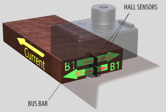
Figure 2: Current measurement without toroidal core
B1= Magnetic flux, induced by current
B2 = Magnetic flux leakage
B1= Proportional to current
The output signal of the Hall sensors is proportional to B
The output signal of the current sensor is proportional to: B1 x (-B1) +B2 x (+B2) = 2B1
This is why we speak of a high degree of immunity to uniform flux leakage.
The conventional approach to differential current measurement involves installing a sensor on each side of the conductor. Raztec recognized that it would be advantageous to measure the current inside the bus bar by drilling into it or – to put it another way – sounding it out. This is where the name Current Probe for this innovative sensor comes from, shown in Figure 3 here.
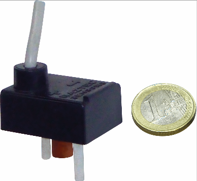
Figure 3: The Current Probe from Raztec
Probe instead of Converter
The format of the probe allows a considerable reduction in the size and weight of the sensor. In fact, the smaller the sensor, even the better. Figure 5 clearly illustrates the considerable difference in size compared to a classic push-through sensor. The one-sided mounting of the probe considerably simplifies tapping of the current.
In principle, the sensor can even be retrofitted without dismantling the bus bar. As the current increases, the cross-section of the bus bar increases, too, which means that the magnetic flux changes only slightly. Therefore, the current probe can remain unchanged even at higher currents: It can measure 1,000 A as well as 25,000 A.
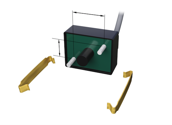
Figure 4: Mounting options
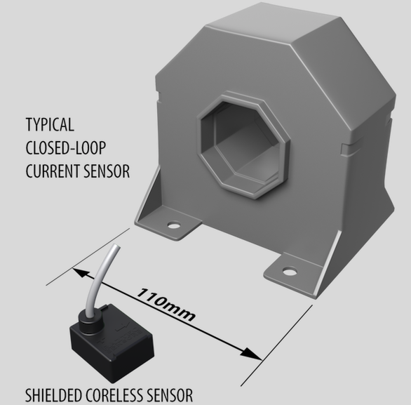
Figure 5: Size comparison with a conventional current sensor
But engineers also know the proverb: there is no rose without thorns. Differential magnetic field measurement is not the perfect answer to eliminate the effects of stray fields. It is effective in uniform fields such as the terrestrial magnetic field. But the fields induced by adjacent conductors are usually not uniform.
Fortunately, these effects can often be neglected because magnetic field sensors are insensitive to fields acting outside their axis. If the current sensors are positioned in such a way that the stray fields do not act axially, their effects can be minimized. Figure 6 shows a simple configuration. As already mentioned, interference immunity can also be increased by tapering the conductor and thus amplifying the magnetic field to be measured and the sensor output at the same time.

Figure 6: Simple configuration on bus-bars
Special Challenges
Mounting of the Probe
In some applications, the mounting of the probe on the bus bar is a challenge. It is obvious that no conductive fasteners should be used for the probe. For this reason, nylon screws are supplied and Nyloc nuts (see Figure 4) would be the optimum counterpart. However, not all engineers trust this connection. High-temperature adhesive pads are therefore integrated as an alternative or supplement. If you don’t trust them either, you still have locking devices available for clips. Saddle clamps are another possible “low-tech” solution.
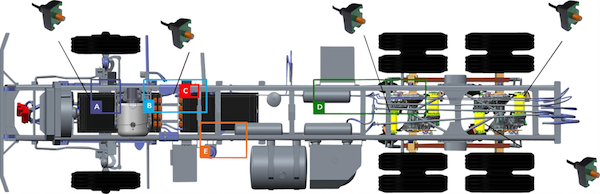
Figure 7: Application example hybrid drive for trucks
A further challenge for sensors without toroidal cores – and to a certain extent for all current sensors – is their sensitivity to rapidly changing electrical fields, such as those generated by PWM high-voltage signals. When designing the current probe, great importance was therefore attached to effective electrostatic shielding of the electronics. Hence all sensitive components are enclosed in a Faraday cage.
High Temperature
The high temperature is another challenge: In order to save costs, bus bars are often designed in such a way that they become hot during operation. The probe must be placed on these hot conductors. This requires the selection of components that ensure high reliability and stability at high temperatures. In addition, the ensemble is then encased in a silicone-based high-temperature capsule. The probe is specified for temperatures up to 125°C, with temperature peaks up to 150°C. This is very unusual for current sensors. Of course, the encapsulation also provides a hermetic seal and is insensitive to strong vibrations.
The output signal of the probe depends on the size and shape of the conductor on which it is mounted. Therefore, Raztec can simulate any conductor for calibration purposes and calibrate any produced sensor accordingly. This makes the current probe a unique customized programmed and calibrated current meter.
Possible Applications
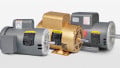
A primary application is certainly the measurement of phase currents in electric motors, especially in automotive environments where space conditions are always critical. Low weight is also important, as the vehicle mass has a direct influence on energy consumption.
The current probe is also suitable for monitoring charge and discharge currents on batteries for protection purposes or to indicate the state of charge. Hybrid vehicles cover the entire range of current measurement – from the engine to the generator to the battery. The Wrightspeed hybrid drive for trucks is an excellent example of this (see Figure 7), in which current probes are installed at various positions.
Summary
The new current probe from Raztec is ideally suited for measuring even very high current intensities, with a small size and at low cost. It is extremely easy to use and to install and offers a high level of protection against interference such as high temperatures, water, vibration, or electromagnetic radiation
About the Authors
Warren Pettigrew holds a Bachelor's Degree in Electrical and Electronics Engineering at Canterbury University. He worked at Raztec as the Chief Technical Officer. Currently, he works at the Dynamic Controls as the Senior Research Engineer.
Mr Leggio has significantly expanded the electrical power supply product range since joining Pewatron AG in Zurich on 1 January 2000 and is now responsible for product management and account management for the electrical power supply, current sensors and active differential probe divisions. He has built up a great wealth of knowledge, which he applies to the benefit of all customers.
This article originally appeared in the Bodo’s Power Systems magazine.