Facebook
 Google
 GitHub
 Linkedin
How to Control Brushless DC Motors
Brushless DC motors are widely used in consumer appliances, industrial equipment, and automotive applications. While they offer a more reliable and maintenance-free alternative than conventional brushed motors, they require more complex electronics. This article investigates the techniques driving brushless DC motors, sensor methods, and popular algorithms.
This article is published by EE Power as part of an exclusive digital content partnership with Bodo’s Power Systems.
Brushless DC (BLDC) motors have become extremely popular over the last decade. They are probably even more ubiquitous than Wi-Fi, and you might be surprised how many are in the items around your home, office, and car. Allied Market Research estimates that the global market for brushless DC motors will reach $ 72.2 billion by 2030, up from $33.2 billion in 2020 (Figure 1). Its ‘Brushless DC Motors Market Research, 2030’ research report predicts a 10.3 percent CAGR across all motor ratings, with the 750W to 3000W category experiencing the most significant increase.
Brushless Motor Applications
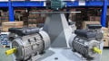
BLDC motors suit various applications, from battery-powered power tools to domestic vacuum cleaners, radio-controlled drones, and electric vehicles. The industrial sector uses them in the hundreds, from conveyor belts to production robots.

Figure 1. Growth in BLDC motors 2020 - 2030 - from Allied Market Research report (Source: AMR - https://www.alliedmarketresearch.com/ brushless-dc-motors-market - permission requested). Image used courtesy of Bodo’s Power Systems [PDF]
BLDC motors are popular due to their low maintenance attributes. They have high energy efficiency, typically up to 92 percent, at least 10 to 15 percent more than a brushed motor of the same size. In addition, BLDCs can operate at higher speeds due to the lack of friction from any brushes. The lack of brushes also contributes to a more compact size, a low audible noise attribute, and a significantly reduced EMI profile. These characteristics make them the ideal motive drivetrain component for electric vehicles, where the high torque and high-speed capabilities are crucial.
However, the benefits of a BLDC should be balanced with their higher cost and complex drive requirements. Figure 2 compares different popular motor configurations, highlighting their pros and cons. Although slightly different in their operation and the internal construction of the stator windings, BLDCs are similar to permanent magnet synchronous motors (PMSM).

Figure 2. Popular DC motor types illustrating key advantages and disadvantages (Source: Qorvo). Image used courtesy of Bodo’s Power Systems [PDF]
How Does a Brushless DC Motor Work?
Before we delve into the operation of a BLDC or PMSM, let’s briefly explain some essential motor terminology:
Windings: Coils of copper wire placed either on the stator or rotor. They function as electro-magnets, generating a magnetic field according to the direction of current flow. The three windings of the BLDC in Figure 2 can be wired in series to create a single-phase motor or wired individually for a three-phase BLDC.
Rotor: The rotating part of the motor. Windings around the rotor receive energy via the brushes in a brushed motor. The windings are on the stator in a brushless motor, and permanent magnets surround the rotor. A small air gap exists between the rotor and the stator.
Stator: The non-rotating part of the motor part of the casing. Figure 2 illustrates the stator’s magnetic poles of a brushed motor. Compare this to the BLDC, where the stator contains the non-rotating windings.

Figure 3. A comparison of the back-EMF waveforms created by BDLC and PMSM motors (Source: Qorvo). Image used courtesy of Bodo’s Power Systems [PDF]
Commutation: The method of alternating the direction of current flow in a winding to achieve rotation.
Back-EMF: Back-electromotive force is the electrical energy created in a winding as it passes through a magnetic field. In the case of a BLDC, the back EMF comes from the rotor’s permanent magnets. Back-EMF can be used to sense the rotor’s position relative to the stator windings and, therefore, to drive the commutation process.
The difference between a PMSM and a BLDC is primarily the shape of their stator windings and, consequently, the characteristics of the back-EMF waveform created (Figure 3).
Motor Drive Algorithms and Sensors
Achieving rotation in a BLDC or a PMSM involves commutation with drive signals applied to the stator windings. Semiconductor-based motor drive controllers - commonly called drives - create waveforms, the number of which and their shape are determined by the motor type and the number of phases. As Figure 3 illustrates, a BLDC motor suits a trapezoidal-shaped drive waveform compared to a sinusoidal approach with a field-oriented (FOC) control approach for the PMSM. In a three-phase PMSM, commutation utilizes three sine-wave waveforms phased 120 degrees apart. A BLDC motor can also be driven using a sinusoidal waveform.
Whether using an FOC or a trapezoidal drive, effective rotor control requires knowing precisely where the rotor is relative to the stator windings. This provides essential feedback to the motor drive, controlling motor speed and torque. The positional information determines the drive signals’ sequencing, timing, and frequency.
Two methods exist to determine the rotor position: sensor or sensorless.
Sensor: Hall-effect sensors placed beside each stator winding - the small blue squares in Figure 2 - detect the changes in magnetic field polarity (N to S, S to N) as the rotor rotates. A three-phase motor requires three sensors.
Sensorless: Instead of using sensors, a sensorless approach determines the rotor’s position using the back-EMF.

Figure 4. A simplified diagram of a three-phase BDLC motor using Hall-effect sensors to create the commutation process and sequence the inverter operation (Source: Qorvo). Image used courtesy of Bodo’s Power Systems [PDF]
There are pros and cons to each sensing method. Using Hall-effect sensors involves additional component costs and more assembly time. However, sensored BLDC/PMSM motors offer excellent torque, smooth rotational motion, and high efficiency. The drive controller for a PMSM tends to be more complex and using FOC demands the use of sensors.
The sensorless approach is prevalent for BLDC motors, resulting in attractively priced motors, but creates a requirement for algorithms to determine rotor position from the back-EMF induced in the stator windings. One challenging aspect of a sensorless BLDC motor occurs at start-up. Without any movement, there is no back, so calculating the rotor’s position must be achieved another way. Typically, high-frequency drive signals are fed to each phase winding, and an algorithm calculates the position accordingly.
Figure 4 highlights a simple three-phase BLDC motor configuration using Hall-effect sensors - HSW, HSV, and HSU. The sensors are essentially digital switches, indicating the polarity of the detected magnetic field, with north equal to ‘1’ and south ‘0’. The output of the three sensors is combined to give a 3-bit digital logic ‘opcode,’ indicating the rotor’s position and the direction as it changes. This information provides the basis of the drive signals to the three-phase power transistor inverter stage. For relatively low-power BLDC applications, the sensor interface, motor controller, and drive transistors are typically integrated into a single controller IC. High-power motors typically take the gate drive output from the controller IC and employ heatsinked power MOSFETs to achieve the desired drive current.
To vary the motor’s speed, a pulse-width modulation (PWM) technique changes the duty cycle - the ratio of pulse on/off. This method is also advantageous during the motor start to limit the start-up current.
BLDC Motor Drive ICs and Development Resources
Figure 5 illustrates the functional block diagram of a low-power sensorless three-phase BLDC motor driver, the TI DRV10963. Incorporating three power MOSFETs, the IC accommodates BDLC motors up to 5 V / 0.5 A for driving cooling fans used in laptops and on high-performance processors. The DRV10963 features short circuit and over-current protection provided by monitoring the current and voltage of each MOSFET through a multiplexed analog-to-digital converter (ADC). A PWM input can control the motor speed to achieve the desired motor speed. The ‘FR’ input allows changing the motor direction at start-up, and the ‘FG’ output provides motor speed information.

Figure 5. The functional block diagram of the TI DRV10963 5 V three-phase sensorless BLDC motor driver (Source: TI). Image used courtesy of Bodo’s Power Systems [PDF]
Microchip offers a comprehensive line-up of single-chip BLDC motor drivers and gate driver ICs. An example is the MCP8063, a 3-phase brushless sinusoidal sensorless motor driver designed for automotive cooling fan and pump applications.
The Qorvo PAC5532 power application controller suits a wide range of high-speed consumer, industrial, and automotive motor control applications, including battery-powered power tools, e-bikes, and light hybrid electric vehicles. Suitable for use with 48 VDC to 120 VDC systems, the PAC5532 integrates a 150 MHz Arm Cortex-M4F 32-bit core with comprehensive and configurable power management and drive functions(Figure 6).

Figure 6. A simplified application block diagram of the Qorvo PAC5532 in battery-powered motor control applications (Source: Qorvo). Image used courtesy of Bodo’s Power Systems [PDF]

Figure 7. Illustrates the major components of the evaluation kit, including the PAC5532 and the three-phase half H-bridge inverter components. A GUI-based software development kit is available for download from the Qorvo website. (Source: Qorvo). Image used courtesy of Bodo’s Power Systems [PDF]
Complementing the PAC5532 is the Qorvo PAC5532EVK1 evaluation kit.
Another motor control IC is the high-performance Renesas RA6T2 microcontroller series. Based on a 240MHz Arm Cortex-M33 microcontroller core, the IC includes a hardware-based accelerator for speeding up complex motor control algorithms and running secure cryptographic functions. A full-featured set of analog functions includes a 12-bit analog-to-digital converter (ADC), a 12-bit digital-to-analog converter (DAC), programmable gain amplifiers, and highspeed comparators (Figure 8).

Figure 8. The functional block diagram of the Renesas RA6T2 microcontroller-based motor controller IC (Source: Renesas). Image used courtesy of Bodo’s Power Systems [PDF]
The Renesas MCK-RA6T2 evaluation kit provides a convenient and practical method of prototyping a brushless motor driver design. Comprising three connecting boards – inverter, microcontroller, and communications – the kit also includes a small brushless DC motor and all required cables. The functional architecture of the MCK-RA6T2 is illustrated in Figure 9.

Figure 9. A functional block diagram of the Renesas MCK-RA6T2 brushless motor evaluation kit (Source: Renesas). Image used courtesy of Bodo’s Power Systems [PDF]
Getting Started with BDLC Motor Control
Here, we've explored how brushless motors operate, why they are popular, and some example use cases. The leading semiconductor solutions showcased in the last section offer a convenient, well-documented, and trusted approach to getting you started with your first BDLC/PMSM design.
This article originally appeared in Bodo’s Power Systems [PDF] magazine.