Facebook
 Google
 GitHub
 Linkedin
IGBT Modules With SLC+ Technology: A Strong Fit for Wind Converter Designs
Engineered for modern wind converter applications, LV100 IGBT modules with SLC+ technology support high efficiency, improved power-cycling capability, and robust long-term operation from established 690 Vac converter systems to emerging 1000 Vac / 1500 Vdc designs.
This article is published by EEPower as part of an exclusive digital content partnership with Bodo’s Power Systems.
Wind energy remains one of the most important pillars of the global energy transition. As turbine ratings continue to increase and cost pressure remains high, the electrical conversion stage becomes even more critical. The converter must efficiently transfer energy between the generator and the grid while maintaining stable operation over many years in demanding outdoor environments.

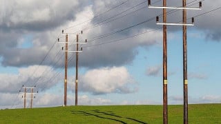
Image used courtesy of Freepik
In practice, wind converter designers must balance several major targets at the same time: reliability, compactness, scalability, efficiency, and system cost. These design targets are strongly linked. A converter with poor efficiency needs more cooling, a converter with insufficient reliability increases service cost, and a converter with weak scalability makes platform reuse difficult.
These system-level targets translate directly into requirements for the IGBT power module. The module must provide low conduction and switching losses, strong resistance to thermal and power cycling, high robustness against cosmic-ray-induced failures, and a package concept that supports compact, manufacturable converter designs. In wind applications, these requirements are important because variable wind conditions create fluctuating thermal loading [1], and low generator frequencies result in junction-temperature ripple in power semiconductors.
LV100 Power Module Family
The LV100 package is a well-established platform for high-power industrial and renewable-energy converters. Its compact outline, standardized mechanical concept, and low internal stray inductance support robust converter design with good switching behavior. For wind applications, the LV100 family offers an attractive basis for compact and scalable power stages.
Within the wind-relevant range, two voltage classes are especially important. The first is the 1.7 kV class, which remains a strong choice for established 690 Vac converter systems. The second is the newer 2.5 kV class, which targets higher-voltage systems up to about 1000 Vac and 1500 Vdc while still enabling a simple two-level topology.
Two representative modules with SLC+(plus) technology are therefore of particular interest. The 1.7 kV / 1800 A CM1800DWA-34TE is well suited for 690 Vac wind converter platforms. The new 2.5 kV / 1200 A CM1200DWA50TE addresses higher-voltage converter concepts and new system trends toward 900 Vac to 1000 Vac operation. By enabling higher converter voltage, the 2.5 kV class helps reduce output current for a given power level. This supports higher power density, lower conductor stress, and more favorable overall converter optimization.
SLC+ Package Technology: Reliability for Wind Converter Mission Profiles
A major reliability contribution of the industrial LV100 concept is the SLC package structure. Compared with conventional module construction using ceramic substrate and silicone-gel encapsulation, SLC uses an insulated metal substrate and resin encapsulation. This directly addresses one of the classical weak points of conventional power modules: thermomechanical stress caused by mismatched thermal expansion inside the package material stack [2][3].
In conventionally constructed modules, solder and ceramic-related interfaces can degrade under repeated thermal cycling. By contrast, the SLC concept uses an insulating structure whose thermal expansion is closely matched to copper, and the system solder in the package structure is eliminated. This significantly improves thermal-cycle capability and results in extended field lifetime. For wind converters, this matters because the thermal load is dynamic. Wind fluctuations, varying torque, grid interaction, and converter operating transitions all create changing thermal conditions in the power stage.
The resin encapsulation in SLC also helps create a more even stress distribution around the bond-wire connection than softer gel-based structures. This forms the basis for higher power-cycling robustness and provides the starting point for the further reliability gains achieved with SLC+.
While SLC already provides a strong reliability basis, wind converter mission profiles can require an additional step in power-cycling robustness. This is especially true on the generator side, where low electrical output frequencies can lead to pronounced junction-temperature ripple. In rotor-side operation, frequencies in the range of about 5 to 10 Hz can make the thermal swing of the chips, and especially of the diodes, a key lifetime driver.
To address this, Mitsubishi Electric developed the SLC+(plus) structure. SLC+ builds on SLC and adds two essential improvements:
a new Al-alloy bond wire with much higher mechanical strength than conventional Al wire, and a hard metallization layer on the chip surface. Together, these measures significantly improve the power-cycling capability. The stronger Al-alloy wire reduces crack growth, while the hard metallization layer prevents the weak point from shifting from the wire to the chip surface [4].
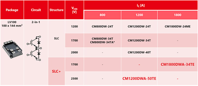
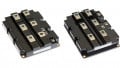
Figure 1. Industrial LV100 IGBT Module Line-up. Image used courtesy of Bodo’s Power Systems [PDF]
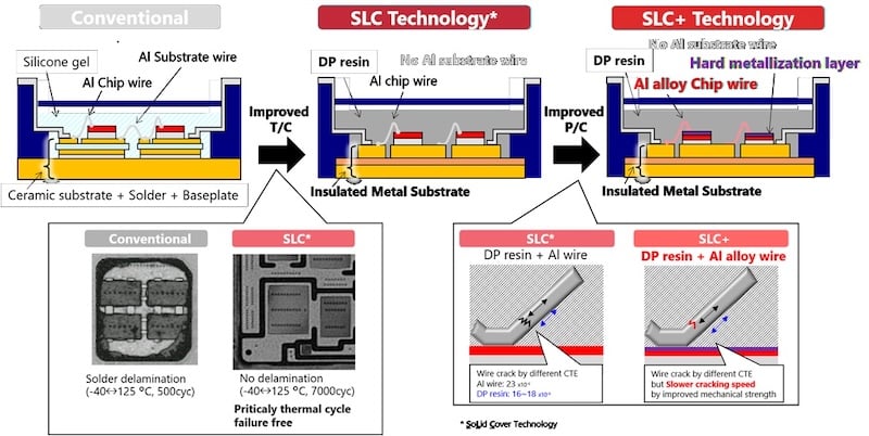
Figure 2. SLC+ Technology in comparison to SLC and conventional package technologies. Image used courtesy of Bodo’s Power Systems [PDF]
Power-cycling tests are still ongoing under several conditions. For example, with a ΔTj swing of 100 K, more than 30 million cycles without failure have been performed, and the test is ongoing. Comparing the SLC+ power cycle performance with SLC and conventional modules, a significant improvement of a factor greater than 4.5 has already been identified. Therefore, it is clear that SLC+ is especially well suited for mission profiles with temperature ripples caused by low generator frequency in combination with potential wind load fluctuations, as found in wind converters.
In addition to the power-cycling improvement achieved by SLC+ technology, the module design and material system are qualified for an increased continuous operating junction temperature from Tvjop(max) = 150 °C to Tvjop(max) = 175 °C. This additional 25 K temperature margin can be used to increase the available output power of the module. In the example shown in Figure 4, this results in a 14% increase in output power capability.
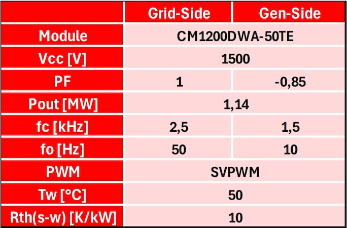
Figure 3. Operating conditions for wind converter grid and generator side, full-scale B2B. Image used courtesy of Bodo’s Power Systems [PDF]
Output Capability, Losses, and Thermal Performance
To evaluate the application performance of the new 2.5 kV LV100 module, the CM1200DWA-50TE was simulated under operating conditions considered typical for a direct full-scale back-to-back wind converter. The analysis assumes a three-phase converter with an output voltage of 1000 Vrms and space vector PWM (SVPWM).
For the grid-side converter, unity power factor and a switching frequency of 2.5 kHz were assumed. For the generator-side converter, the operating point was defined by a power factor of -0.85 and a switching frequency of 1.5 kHz. In addition, a water temperature of 50 °C and a thermal resistance from heatsink to water of 10 K/kW were assumed. This cooling condition was verified by a heatsink manufacturer for the LV100 module.
These conditions reflect the different requirements on the two converter stages in a full-scale wind power system. The grid-side converter typically operates close to unity power factor and at a higher switching frequency in order to enable low harmonics and smaller filter inductors on the grid side. The generator-side converter, in contrast, is characterized by negative power factor operation and a lower switching frequency. From the power-module point of view, this means that grid side and generator side impose different electrical and thermal loading profiles, and a suitable wind-converter module should ideally handle both in a balanced way.
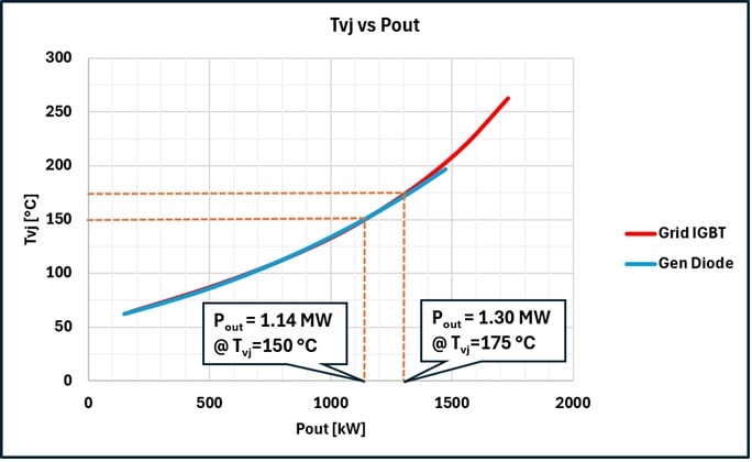
Figure 4. Output power capability of 1200 A/2500 V LV100 (CM1200DWA-50TE). Image used courtesy of Bodo’s Power Systems [PDF]
The calculated junction-temperature curves versus output power show that both converter sides reach a junction temperature of 150 °C at the same output power. In this example, it corresponds to 1.14 MW for a three-phase converter using three LV100 modules per converter side without any parallel connection. This represents the highest power density for a converter in this class. When the module’s maximum operating junction temperature of Tvjop(max) = 175 °C is considered, the available output power increases to 1.3 MW.
An important outcome of the simulation is that the module is thermally well balanced for both operating modes of the back-to-back converter. On the generator side, the diode represents the thermally critical device, whereas on the grid side the IGBT is the limiting device. Even though the limiting chip type is different, both converter sides reach the same output power at the same maximum junction temperature. This demonstrates that the CM1200DWA50TE is well optimized for both generator-side and grid-side operation.
From a system perspective, this is a significant practical advantage. The converter designer does not need to use two different power-module types for the two converter stages. One common module type can be used for both sides of the back-to-back converter, which simplifies converter design and brings logistical benefits in sourcing, stock management, and service.
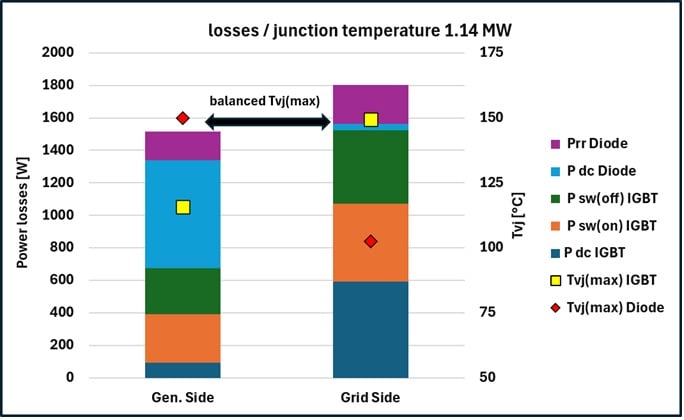
Figure 5. CM1200DWA-50TE losses and temperatures at 1.14 MW output power. Image used courtesy of Bodo’s Power Systems [PDF]
At the operating point of 1.14 MW, the calculated semiconductor efficiency is 99.2% on the generator side and 99.05% on the grid side. These values confirm that the 2.5 kV LV100 module combines high output capability with high efficiency in both operating modes. It should be noted that these values include semiconductor losses only. Additional system losses from filters, busbars, cabling, cooling auxiliaries, or other passive components are not included in this comparison.
Overall, the results demonstrate that the CM1200DWA-50TE is a strong fit for wind converters. It combines high output capability, very high power density, and a well-balanced thermal design for both generator-side and grid-side operation, while also enabling the practical use of one common module type across the full converter.
Robustness Against Cosmic Ray-Induced Failures
Long-term DC stability (LTDS) and robustness against cosmic-ray-induced failures are important design criteria for modern wind converters. This is not only a topic for installations at high altitude. Even at sea level, long-term operation at high DC-link voltage can lead to statistically relevant failure rates, especially in converters designed for many years of continuous operation.
This is particularly important in offshore wind power systems. In such installations, maintenance is very costly and logistically demanding, often requiring vessel access or even helicopter service. At the same time, wind turbines have very high power ratings, and the associated converters contain a large number of power modules. As a result, LTDS must be considered not only at device level, but also at full converter-system level.
For this reason, lower-voltage alternatives such as 2300 V modules are not always sufficient for long-term 1500 Vdc operation. Our system-level estimation shows a clear difference between 2300 V and 2500 V solutions. For a 1000 Vac / 1500 Vdc, 6 MW wind converter system with 30 installed modules and a 20-year operating period, the calculated system failure probability is about 0.53% for the 2500 V Mitsubishi Electric solution, compared with about 53% for a 2300 V class alternative.
This result shows that the choice of module voltage class is not only a matter of blocking-voltage margin, but a key reliability decision for long-term wind-converter operation. Especially in offshore applications, where service effort is extremely high, strong LTDS robustness is essential.
Summary
Wind converters require power semiconductor modules that combine high efficiency, compactness, and long-term reliability and robustness. The LV100 platform addresses these requirements for both established 690 Vac systems and newer 1000 Vac / 1500 Vdc converter designs.
With SLC+ technology, the LV100 module improves power-cycling capability by combining resin encapsulation, Al-alloy bond wires, and hard chip metallization. The module is also qualified for continuous operation up to Tvjop = 175°C, enabling higher output power density. This makes it especially suitable for wind converter mission profiles with fluctuating load, low generator-frequency-related junction-temperature ripple, and high-power-density demand.
Simulation results for the 2.5 kV module CM1200DWA-50TE show a well-balanced design for both generator-side and grid-side operation. In the analyzed full-scale back-to-back converter example, both sides reach 1.3 MW, with semiconductor efficiencies above 99%. This enables the use of one common module type for both converter stages.
Finally, strong LTDS robustness is essential for long-term wind-converter reliability. Here, the 2.5 kV solution offers a clear advantage over lower-voltage alternatives, making it a strong fit for modern wind power converters.
References
[1] Li Hui et al., “Power Cycling Capabilities Assessment of IGBT Modules in Wind Power Converter Considering the Wind Turbulence Effects,” IEEE PEAC, 2014.
[2] Takuya Takahashi et al., “A 1700V-IGBT Module and IPM with New Insulated Metal Baseplate (IMB) Featuring Enhanced Isolation Properties and Thermal Conductivity,” PCIM Europe, 2016.
[3] Thomas Radke et al., “More Power and Higher Reliability by 7th Gen. IGBT Module with New SLC-Technology,” Bodo’s Power Systems, August 2015, p. 24 ff.
[4] Tsuyoshi Uraji et al., “Increase of Power Cycling Lifetime in Power Semiconductor Modules Applied Fine-Grained Al Alloy Wire,” MATE, 2022.
[5] Akiyoshi Masuda et al., “2.5 kV IGBT Module with High Reliability for Renewable Applications”, PCIM Europe, 2024.
[6] Tomokazu Kanna et al., “2.5 kV IGBT Module with High Withstand Voltage and High Reliability”, PCIM Europe, 2026.
This article originally appeared in Bodo’s Power Systems [PDF] magazine.