 Facebook
 Google
 GitHub
 Linkedin
800 VDC to the AI Server: A Modular GaN Route To Low-Voltage Rails
A modular ISOP architecture with low-voltage GaN devices efficiently transforms 800 VDC rack power into high-current processor rails (50V, 12.5V, 6.25V) with up to 98.5% peak efficiency.
Article co-authored by EPC’s Alejandro Pozo and Ionel “Dan” Jitaru, CEO, Rompower Energy Systems
This article is published by EEPower as part of an exclusive digital content partnership with Bodo’s Power Systems.
AI servers are forcing power architectures to move in two directions at once: toward much higher distribution voltage and toward much higher processor power requirements. An 800 VDC rack bus can reduce distribution losses, but it also creates a demanding conversion problem: thousands of watts must be transformed efficiently into low-voltage, very high-current rails close to the load.
A modular input-series, output-parallel (ISOP) architecture offers a path. By dividing the 800 V input among eight LLC stages and combining their outputs, it enables the use of fast, low-voltage GaN devices while distributing heat and current. Three implementations illustrate the approach.
What Is An ISOP Converter And How Does It Work?
The ISOP architecture is a modular approach based on several identical isolated DC-DC converter modules, which use an LLC resonant topology. In this configuration, the modules' outputs are connected in parallel and the inputs in series. This is a nice way to scale the input voltage and output current simultaneously. A system with M modules has each module receiving only a fraction of the total input voltage (VIN/M) and processing a fraction of the total output power (POUT/M). One of the important advantages of LLC-based modules in an ISOP string is the self-balancing of modules.
The converter gain is almost constant at resonance when the ratio of the magnetizing inductance to the resonant inductance is properly selected. This gives a robust solution insensitive to component tolerances and avoids the need for complicated control algorithms for voltage and current sharing. Besides, the modular architecture allows the LLC modules to be interleaved in phase, significantly reducing the output current ripple. For example, a 6 kW, 800V to 12 V single LLC module has about 754 A peak-to-peak ripple, whereas a four-module interleaved ISOP reduces it to 37 A, significantly reducing the output bus capacitance requirement.
Splitting the 800 V Problem into Manageable Building Blocks
The central idea behind ISOP is straightforward: instead of asking one converter to withstand the full 800 V bus, the architecture shares the input voltage across multiple converter cells. In the designs discussed here, eight LLC modules are connected in series on the input and in parallel on the output. Each module therefore sees about 100 V, while the output currents add together.
This changes the semiconductor design space. Lower-voltage GaN transistors can efficiently switch at around 1 MHz, reducing switching and conduction losses compared with a solution based on higher-voltage devices operating at lower frequencies. The eight phases also distribute power dissipation, simplify thermal management, and reduce the output capacitance required through interleaving. Transformer construction benefits as well because each individual stage handles only a fraction of the total voltage.
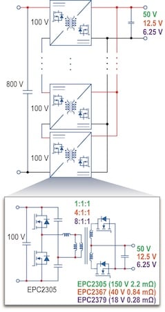
Figure 1. ISOP block diagram showing the eight LLC stages and the detailed converter-cell implementation. Image used courtesy of Bodo’s Power Systems [PDF]
The modular structure also provides flexibility beyond the specific 800 V implementation. The same architecture can be adapted to lower-voltage input configurations by changing the number of modules and their operating voltage. This makes the approach less dependent on a single rack-voltage standard and provides a development path as data-center power distribution evolves. The first demonstration targets an 800 V-to-50 V conversion at 11 kW. Each LLC processes 100 V and 1.375 kW. The primary half-bridge and center-tapped secondary use the same 150 V GaN transistor, EPC2305, rated at 2.2 mΩ typical on-resistance. A 1:1:1 transformer and a resonant operating point near 1 MHz complete each module.
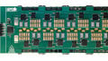
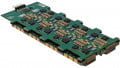
The mechanical implementation is equally important. Rather than building eight completely separate converters, two LLC stages are integrated into each PCB and magnetic structure. Four vertical boards therefore accommodate the eight modules, with a horizontal control board underneath. Compared with the earlier 400 V-to-50 V implementation, this approach doubles power density while reducing the volume of the magnetics by approximately half.
The measured results demonstrate the potential of the architecture: the 50 V converter reaches 98.5% peak efficiency and 98% efficiency at full load while processing up to 11 kW.
Going Directly from 800 V to the Processor Rails
The same architectural concept can be pushed much further. A second converter moves directly from 800 V to 12.5 V, delivering 6 kW. With an overall 64:1 ratio, each of the eight LLC stages converts 100 V to 12.5 V and delivers as much as 750 W. Parallel connection at the output produces up to 480 A.
Here, the combination of ISOP and GaN becomes particularly significant. EPC2305 devices remain on the 150 V primary side, while EPC2366 devices, rated at 40 V with 0.8 mΩ typical on-resistance, are used as synchronous rectifiers. The transformer uses a 4:1:1 turns ratio and is integrated into a 14-layer PCB.
Packaging becomes almost as important as electrical performance at these current levels. The complete converter occupies less than 5000 mm² of PCB area and is only 8 mm thick. The GaN devices are mounted on the top side, allowing direct thermal coupling to a heat spreader or water-cooled cold plate. The converter achieves more than 98% peak efficiency and 97% efficiency at full load while delivering 480 A.
The third design addresses an even more demanding rail: 6.25 V. It again uses eight LLC modules, but now the overall ratio is 128:1. Each cell converts 100 V to 6.25 V and can deliver 750 W, or 120 A. In parallel, the converter reaches 960 A at 6 kW.
At this voltage, every milliohm matters. The design therefore moves to EPC2376 150 V GaN devices on the primary and EPC2379 devices on the secondary. The EPC2379 has a typical on-resistance of just 0.33 mΩ and four devices in parallel are needed to handle the extreme output current. The PCB uses a 6+6-layer construction in the original design, with an 8+8-layer configuration planned for the next revision. An 8:1:1 transformer ratio and multilayer PCB structures are used to control the leakage inductance within the available mechanical height, eliminating the need for a dedicated external leakage inductor.
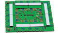
The physical layout reflects the electrical challenge. Eight power cells are distributed around the board perimeter, close to the current-extraction points. Edge metallization provides a low-impedance path for the combined output current, helping reduce conduction losses. The complete assembly is 11 mm thick and occupies about 15,400 mm² of PCB area.
Across the three implementations, the output voltage falls by a factor of eight - from 50 V to 6.25 V - while the output current rises dramatically. That progression highlights a fundamental system-level tradeoff: at lower voltage, the converter is increasingly dominated by conduction losses, current distribution, interconnect resistance, and thermal paths. The designs address these issues through coordinated choices in GaN transistors, transformer ratios, PCB integration, parallel rectification, and current extraction.
The experimental results remain consistent: the 6.25 V converter achieves more than 98% peak efficiency and 97% efficiency at full load, while delivering up to 960 A.
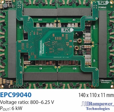
Figure 2. Picture of the 800 V-to-6.25 V converter, showing the compact multilayer implementation and distributed power cells. Image used courtesy of Bodo’s Power Systems [PDF]
Conclusion
The eight-module ISOP architecture turns an 800 V bus into a set of manageable 100 V conversion cells, while parallel outputs provide the enormous currents demanded by modern processors. The results - up to 11 kW at 50 V, 6 kW at 12.5 V, and 6 kW at 6.25 V, with peak efficiencies above 98% - demonstrate the scalability of the approach. As AI rack power continues to increase, the challenge will not simply be moving more power. It will be doing so within increasingly tight limits on efficiency, thermal management, size, and current density. Architectures that combine high-voltage distribution with compact, efficient, high-frequency GaN conversion offer one way to address that challenge.
This article originally appeared in Bodo’s Power Systems [PDF] magazine and is co-authored by Michael De Rooij, GaN Application Fellow, and Alejandro Pozo, Director of Applications Engineering, Efficient Power Conversion (EPC); and Ionel “Dan” Jitaru, CEO, Rompower Energy Systems