Facebook
 Google
 GitHub
 Linkedin
Identification of PMSM Motor Parameters with a Power Analyzer
This article introduces a method for identifying PMSM motor parameters easily and with a high degree of precision using a power analyzer.
1. Introduction
Recent years have seen permanent magnet synchronous motors (PMSMs) and related control technologies rapidly permeate into the advanced power electronics landscape and markets.
These developments reflect the advent of high-performance, high-efficiency designs thanks to progress in permanent magnet materials as well as the advantages of PMSMs relative to other motors in terms of quiet operation and simplicity of maintenance1). Recently, PMSMs are being adopted in hybrid and electric vehicles in addition to household electronics and industrial machinery, and their entry into widespread use is expected to accelerate in the future2).
In general, PMSM analysis and control are based on the equivalent circuit model for a motor expressed on the d- and q-axes. A variety of high-performance control methods have been proposed for PMSMs, and these control algorithms are based on d-q equivalent circuits, making it extremely important to identify the equivalent circuit constants—in other words, the motor parameters (d-axis and q-axis inductance, Ld and Lq)—with a high degree of precision.
Of these motor parameters, Lq exhibits a particularly high degree of current dependence due to magnetic saturation3, 4), making it difficult to implement high-performance control while using low-precision motor parameters measured in a simple manner with an LCR meter or other instrument while the motor is in the stopped state.
This paper introduces a method by which a power analyzer can be used to identify motor parameters easily and with a high degree of precision while the target motor is operating. In addition, it provides results (motor parameters) obtained through the actual use of this method.
2. Method for identifying motor parameters
This chapter provides a brief description of the principles employed to identify PMSM motor parameters using a power analyzer and of a procedure for doing so.
2.1 Principles
If we assume the following with regard to the voltage equation for a PMSM expressed on the d-q coordinate axis, we arrive at Eq. (2.1)3).
- The spatial distribution of magnetic flux in the gap between the stator and rotor takes the form of a sine wave moving along the gap.
- The harmonic components of the voltage and current can be ignored.
- Core loss can be ignored.
(2.1)
In this equation, vd and vq represent the d-axis and q-axis components of the armature voltage for each phase; i d and i q, the d-axis and q-axis components of the armature current for each phase; R, the armature resistance for each phase; p, the differential operator (d/dt); Ld and Lq, the d-axis and q-axis self-inductance; ω, the rotation angle (electrical angle) speed; and ϕa (=Ke), the RMS value of the permanent magnet’s flux linkage with the armature (i.e., the induced voltage constant).
Fig. 2.1 illustrates the result of assuming a stationary state (so that time-derivative terms can be ignored) and expressing Eq. (2.1) as a d-axis and q-axis vector diagram. In the figure, v1 and i 1 represent the fundamental components of the phase voltage and phase current, and θv and θi represent the fundamental phase angle of the phase voltage and phase current, respectively. Based on Fig. 2.1, the d-axis and q-axis voltage equations can be formulated as follows:
(2.2)
(2.3)
Solving these for LD and Lq yields the following equations:
(2.4)
(2.5)

Figure 2.1: PMSM vector diagram
2.2 Identification procedure
This section describes a procedure by means of which a power analyzer can be used to identify motor parameters.
Although this specific procedure uses a Hioki Power Analyzer PW6001, motor parameters can be identified using a similar procedure with any power analyzer that provides an electrical angle measurement function that is equivalent to that offered by the PW6001.
2.2.1 Measuring the armature resistance R for each phase
Measure the armature resistance R for each phase using a resistance meter or other suitable instrument in advance.
2.2.2 Performing phase zero-adjustment and identifying the induced voltage constant Ke
After placing the motor terminals of the PMSM being measured in the open state (i d = i q = 0), connect the motor terminals to the “CH 1”, “CH 2” and “CH 3” voltage inputs of the Power Analyzer PW6001. Additionally, connect the encoder’s A-phase pulse output to “CH B”, its B-phase pulse output to “CH C”, and its Z-phase pulse (origin signal) output to “CH D” (Fig. 2.2).
Configure the Power Analyzer PW6001’s settings by setting the motor analysis operating mode to “Single,” the measurement parameter to “Torque Speed Direction Origin,” and “CH B” input to “Pulse.” In addition, set the wiring connection for “CH 1”, “CH 2” and “CH 3” to “3P3W3M,” the synchronization source to “Ext1,” and Δ conversion to “ON.” Setting the synchronization source to “Ext1” allows the voltage and current phase angles to be measured using the inputted encoder pulse as the reference, and setting Δ conversion to “ON” allows the line voltage to be converted to, and measured as, a phase voltage.
In this state, drive the motor from the load side to generate an induced voltage and perform phase zero-adjustment on the Power Analyzer PW6001. As a result of this step, θv and θi will represent the phase angle expressed using the phase of the induced voltage generated in the q-axis direction as the reference—that is, the electrical angle.
At this time, Eq.(2.4) can be rewritten as follows since the induced voltage vq is equal to v1, allowing identification of Ke.
(2.6)
In this equation, f 1(=ω/2π) represents the frequency of the phase voltage’s fundamental wave.

Figure 2.2 Wiring connections when performing phase zero-adjustment and identifying the induced voltage constant Ke
2.2.3 Identifying the motor parameters Ld and Lq with user-defined functions
The d-axis and q-axis self-inductance Ld and Lq can be identified using R as measured in Section 2.2.1 and Ke as identified in Section 2.2.2. First, connect the drive inverter output to the motor terminals that were left open in Section 2.2.2 and operate the motor (Fig. 2.3). At this time, the following equations will obtain based on Fig. 2.1:
(2.7)
(2.8)
(2.9)
(2.10)
By configuring the instrument’s user-defined functions (UDFs) with these equations as well as Equations 2.4 and 2.5, it is a simple matter to identify Ld and Lq while monitoring vd, vq, id, and iq. See reference5) for specific examples of settings for the Power Analyzer PW6001’s user-defined functions.

Figure 2.3: Wiring connections when identifying the Ld and Lq motor parameters
3. Measurement example
This section presents the results of using the procedure described in Section 2.2 to actually identify motor parameters.
3.1 Measurement conditions
Tables 1, 2, and 3 describe the specifications of the inverter (Fig. 3.1), drive-side motor, and load-side motor (Fig. 3.2) used in the procedure.
| Item | Specifications |
| Rated output capacity | 10.0 kVA |
| Rated output voltage | 400 Vrms AC |
| Rated output current | 14.5 Arms AC |
| Rated input voltage | 700 V DC |
| Rated input current | 15.1 A DC |
| Maximum input current | 18.6 A DC |
| Input voltage range | 0 VDC to 800 VDC |
| Switching frequency | up to 200 kHz |
| Switching Element | SiC MOSFET |
| Manufacturer | SCH2080KE (ROHM) Myway Plus Corp. |
Table 1: Inverter specifications
Table 4 describes the measuring instruments that were used. The Hioki Resistance Meter RM3544 noted in the table was used to measure the armature resistance R of the drive-side motor listed in Table 2 for each phase (Section 2.2.1).
3.2 Identifying the induced voltage constant Ke
The induced voltage constant Ke was identified using the procedure described in Section 2.2.2.
For reference, Fig. 3.3 illustrates the induced voltage (phase voltage) waveforms for the drive-side motor and A/B/Z phase pulse waveforms for the encoder during the identification process.
| Item | Specifications |
| Model | RM86A20-2-E8 DC brushless motor with encoder |
| Rated voltage | 100 VDC |
| Rated current | 2 A |
| Rated RPM | 2500 rpm |
| Rated output | 120 W |
| Armature resistance for each phase | 0.89768 Ω |
| Number of poles | 8 |
| Number of pulses per rotation | 1024 |
Table 2: Drive-side motor specifications
| Item | Specifications |
| Model | SS60E80-6 DC motor |
| Rated voltage | 100 VDC |
| Rated current | 4.8 A |
| Rated RPM | 2500 rpm |
| Rated output | 350 W |
Table 3: Load-side motor specifications
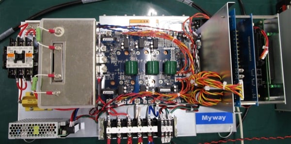
Figure 3.1: Inverter

Figure 3.2: Drive-side motor (left) and load-side motor (right)
| Instrument | Model | Manufacturer |
| Power Analyzer | PW6001 | HIOKI E.E. CORP. |
| Current Sensor | CT6841 | HIOKI E.E. CORP. |
| Resistance Meter | RM3544 | HIOKI E.E. CORP. |
Table 4: Measuring instruments
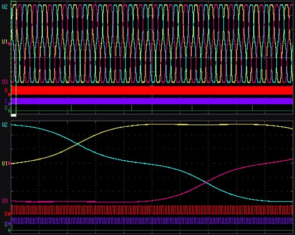
Figure 3.3 Drive-side motor induced (phase) voltage and encoder’s A/B/Z phase pulse waveforms during identification of the induced voltage constant Ke

Figure 3.4: Relationships between the motor rpm n, the RMS value v1 of the fundamental component of the drive-side motor induced (phase) voltage, and the identified induced voltage constant Ke
Fig. 3.4 illustrates the relationships between the motor rpm n, the RMS value v1 of the fundamental component of the drive-side motor induced (phase) voltage, and the identified induced voltage constant Ke. The measured v1 value varies proportionally with n, while the identified Ke value remains roughly constant, without regard to n. In this way, the relationships between these three values can be seen to satisfy the relationships described in Eq.(2.6).
Ke exhibits a small amount of variability during low-speed operation due to the more pronounced rotating unbalance of the motor in that operating regime. 3.3 Identifying the Ld and Lq motor parameters The d-axis and q-axis self-inductance Ld and Lq were identified using the procedure described in Section 2.2.3. For reference, Fig. 3.5 illustrates the inverter’s secondary-side phase voltage and phase current as well as the encoder’s A/B/Z phase pulse waveforms during identification.
Fig. 3.6 illustrates the relationships between (a) the d-axis current id and the identified d-axis self-inductance Ld and (b) the q-axis current i q and the identified q-axis self-inductance Lq. Ld remains roughly constant, without regard to i d. By contrast, Lq exhibits a high degree of current dependency due to magnetic saturation and varies significantly with i q. These characteristics make it clear that it is not possible to use an LCR meter or similar instrument to identify Ld with a high degree of precision while the motor is in the stopped state. Instead, the value must be identified while the motor is operating.
The variability in the Ld and Lq values when the id and iq values are small is also likely to be caused by rotating unbalance of the motor during low-speed operation.
Fig. 3.6 illustrates the results of identifying the Ld and Lq motor parameters while the motor’s rpm is varied while holding the current phase angle constant, showing the current dependence of Ld and Lq. The current phase angle dependence of the motor parameters can also be verified by applying this identification method.

Figure 3.5: Inverter secondary-side phase voltage and phase current and encoder’s A/B/Z phase pulse waveforms during identification of the Ld and Lq motor parameters (when driving the motor with the inverter
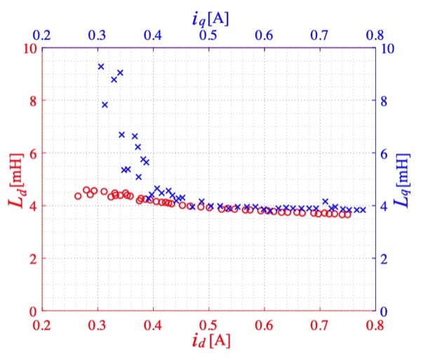
Figure 3.6: Relationships between (a) the d-axis current id and the identified d-axis self-inductance Ld (shown in red) and (b) the q-axis current iq and the identified q-axis self-inductance Lq (shown in blue)
4. Conclusion
This paper has introduced a method for identifying PMSM motor parameters easily and with a high degree of precision using a power analyzer. It also presents the results of using the introduced method along with a Hioki Power Analyzer PW6001 to identify actual motor parameters. It must be noted that the method introduced in this paper presumes the use of an analytical model that posits that core loss can be ignored. That said, by measuring mechanical loss and identifying the equivalent core loss resistance in advance, it would be possible to further develop the described method in order to identify motor parameters while taking into account core loss.
The identification of PMSM motor parameters introduced in this paper is only one example of an application for power analyzers, which can be used effectively in numerous other settings in the power electronics field. The authors look forward in the future to actively introducing other applications in which power analyzers can be effectively.
About Hioki E.E. Corporation
Hioki E.E. Corporation is a Nagano-based company, researches, develops, manufactures, and markets electric measuring devices including resistance meters, automatic testing equipment, and recording equipment. The company's products include integrated circuits (ICs) testers, signal generators, sensors, and power measuring instruments. The company was first established in June 1935, and registered as Hioki E.E. on January 5th, 1952.
References
- Shigeo Morimoto : “Trend of Permanent Magnet Sychronous Machines”, IEEJ Trans, Vol.2 (2007), pp.101-108.
- Investigating R&D Committee on industry applications of PM motors : “Trend in the latest technologies and applications of permanent magnet synchronous motors”, IEEJ Technical Report (2009), No.1145 (in Japanese).
- Shigeo Morimoto, Yoji Takeda, and Takao Hirasa: “Method for Measuring a PM Motor’s dq Equivalent Circuit Constants”, IEEJ Transactions on Industry Applications, Vol.113-D (1993) No.11, pp.1330-1331 (in Japanese).
- A. Soualmi, F. Dubas, D. Depernet, A. Randria and C. Espanet : “Inductances estimation in the d-q axis for an interior permanent-magnet synchronous machines with distributed windings”, Proc. XX ICEM (2012), pp.308-314.
- HIOKI E. E. Corp. : “Identification of PMSM Parameters with the Power Analyzer PW6001” (White paper), retrieved from https:// www.hioki.com/ en/ products/ detail/?product key= 5796.
This article originally appeared in the Bodo’s Power Systems magazine.