 Facebook
 Google
 GitHub
 Linkedin
Complex Numbers, Phasors And Phase Shift
Analysis of AC Systems
The Effect of Phase
We saw in the previous page that the voltage across a capacitor is delayed relative to the current: when a voltage source is first connected to an RC circuit, the current through the capacitor reaches its maximum value right away, but the voltage drop gradually increases toward the maximum value. With inductors, we have the opposite situation: current is delayed relative to voltage.
These delays occur in the context of DC circuits; they convey the response of an inductor or capacitor to the application of a constant voltage. If the supply voltage is continuously varying, as in AC circuits, the delay becomes a phase difference, i.e., an ongoing misalignment between voltage and current. We can also say that the voltage and current are out of phase (if there is no phase difference between them, they are in phase).
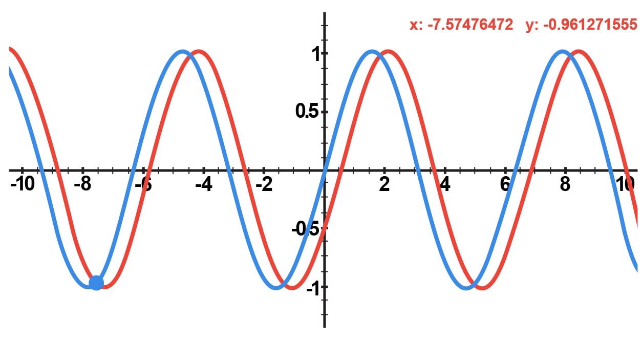
Figure 1. These two AC waveforms have a phase difference of 30°.
The presence of phase differences makes AC circuit analysis significantly more complex than DC circuit analysis.
Let’s say we have a sinusoidal supply voltage with a maximum amplitude of 12 V and a frequency of 60 Hz. We might refer to this voltage as a 12 V, 60 Hz signal. This supply voltage is in series with another supply voltage of the same amplitude and frequency. We want to find the overall voltage, and we might assume that we can simply add the amplitudes together. Unfortunately, the result—i.e., a 24 V, 60 Hz signal—could be seriously incorrect, because this addition does not account for possible phase differences between the two supplies. For example, if the signals have a phase difference of 180°, they completely cancel out, resulting in an overall signal of 0 V.
Leading and Lagging
As explained above, capacitors and inductors create phase differences between a circuit’s voltage and current waveforms. Capacitors and inductors are extremely common components, and consequently phase differences are a fundamental characteristic of AC systems.
The phase relationships created by inductors and capacitors are described using the words leading and lagging. In a DC system, a capacitor’s voltage reaches the maximum value after its current has reached the maximum value; in an AC system, we say that the capacitor creates a situation in which voltage lags current. An inductor has the opposite effect: voltage leads current.
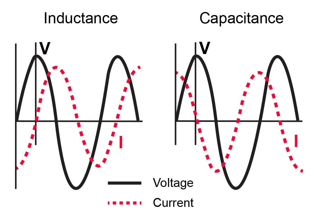
Figure 2. In an inductive circuit, voltage leads current; you can see in the left-hand plot that the voltage waveform reaches its maximum value before the current waveform reaches its maximum value. In a capacitive circuit, voltage lags current, and thus in the right-hand plot the voltage waveform reaches its maximum value after the current waveform has reached its maximum value.
Phasors and Complex Numbers
A sinusoidal waveform with no DC offset can be fully described by an amplitude value, a phase difference (relative to a specified reference signal), and a frequency. Typical AC power systems use only one frequency. In other words, all of the currents and voltages throughout the circuit have the same frequency, and this means that we don’t have to repeatedly account for frequency as we’re analyzing a circuit.
What we need, then, is an analysis technique that allows us to conveniently work with amplitude and phase, because these are the quantities that vary as we move through the circuit. You may already know that complex numbers can be represented as a vector consisting of magnitude and phase, and it turns out that complex numbers are exactly what we need for AC circuit analysis.
A complex number that is used to represent a sinusoidal voltage or current is called a phasor. The magnitude of the phasor is the same as the maximum value of the sinusoidal waveform, and the phase of the phasor is equal to the phase difference between the sinusoidal waveform and a cosine waveform.
Another way of describing the phase component is phase shift, meaning that the phasor conveys how much the signal has shifted relative to a signal that has zero phase. Mathematically, this zero-phase signal is a cosine waveform, but in practice AC signals don’t have a beginning or end, so you choose one of the signals and call it a cosine wave. A logical choice would be the primary input voltage for the system; you could assume that this signal has a phase of zero, and then all the other currents and voltages have a phase shift relative to the primary input voltage.
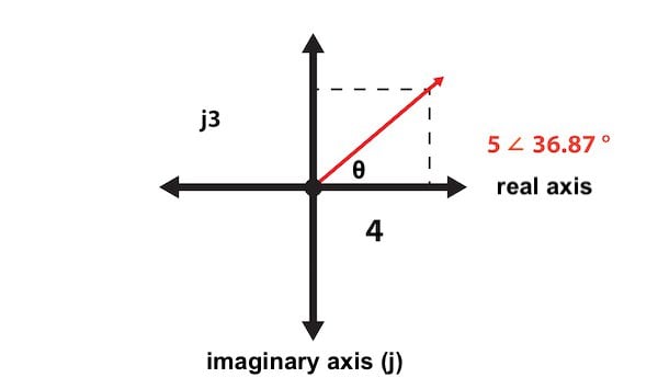
It’s important to understand that phasors are simply a specific application of standard mathematical techniques. A phasor can be represented as a magnitude and angle (this is called polar form); for example, a voltage waveform with an amplitude of 5 V and a phase shift of 36.87° can be written as 5 ∠ 36.87°.
A phasor can also be expressed in rectangular form, i.e., as a complex number consisting of a real part and an imaginary part (in the context of circuit analysis, the imaginary portion of a complex number is preceded by the letter j instead of i). For example:


Thus, the polar-form phasor 5 ∠ 36.87° corresponds to the complex number 4 + j3. If you don’t have much experience with adding, subtracting, multiplying, and dividing complex numbers, please refer to this introduction to complex number arithmetic.
Like any complex number, a phasor can also be represented as a vector. For example:
Next: Calculating Power When Voltage and Current Are Not in Phase
In this page, we introduced an important technique that allows us to conveniently perform circuit analysis in a way that accounts for the phase variations that occur in AC systems.
In the next page, we’ll explore the somewhat complicated task of calculating power when voltage and current are not in phase.