Facebook
 Google
 GitHub
 Linkedin
Highly Reliable Transfer-Molded Power Modules
This article describes a high power IGBT module for electric and hybrid electric vehicle inverters and offers technical concepts and benefits.
Our society is facing a significantly increasing level of electrification. Along with growing electricity consumption, waste of energy must be minimized. The key to energy savings lies in highly efficient power semiconductor devices.
Introduction
Currently, electrification of the powertrain in vehicles is mainly government-driven through subsidy programs or sanctions, and not so much by end-user demand. This will remain unchanged until the cost for electrified driving is lower than driving conventional cars and the possible range has been extended significantly.
For highest efficiency in energy transformation equipment, it is crucial to use ideally adapted power semiconductor devices and equally important for the appropriate first and second level packaging.
Different applications have their own key parameters for best system performance, and hence require power components that are optimized respectively. In particular, automotive e-mobility systems require a deep understanding of system details for defining the right power devices.
This article describes a high power IGBT module for electric vehicles (EV) and hybrid electric vehicles (HEV) inverters.


Figure 1: Bosch power module MH6560C (Source: Bosch)
Many automotive power modules in the market are based on conventional industrial design elements and try to fulfill automotive requirements for reliability. In contrast to that, Bosch focused on automotive requirements, right from the start of the concept definition.
Technical concept
The key parameters for power modules in traction inverters are current density, reliability, and robustness. The combination of high current density and high reliability allows for compact inverter assemblies or for inverter attachment to a motor or gearbox. High robustness simplifies the module handling during inverter assembly. Good thermal performance and low stray inductances are sub-criteria, which allow to further improving the key parameters.
All power semiconductors are contacted through a massive copper substrate (a) and at the top through copper clips (b), with solder joints from both sides (c). The substrate provides excellent heat spreading and improves Rth significantly. It also allows for an extremely low Zth in case of short power pulses. The clips effectively eliminate wire failures. The entire stack is embedded in transfer mold compound (d). A thin insulation layer (e) forms the electrical separation to the large pads at the bottom.

Figure 2: Schematic diagram of Bosch 3rd generation power module MH6560C
Optimized IGBTs
Bosch IGBTs are based on state-of-the-art Infineon chip however the devices have been specifically modeled by Bosch engineers to meet the desired automotive requirements in the best way possible.
A redesigned vertical chip structure further reduces electric power losses. Chip layout, metallization, and passivation of the chip have been adapted to perfectly match the assembly and interconnect technology, resulting in highest reliability, even in extended temperature conditions. An integrated current sensor allows for faster overcurrent protection compared to classic protection approaches based on the IGBT desaturation effect. Failures in the IGBT gate control (e.g. dead time violations) are detected much faster. The current sensor can serve as an external measure (XM, ISO26262) for the functional safety of an inverter system.

Figure 3: low-loss IGBT (Source: Bosch)
Optimized package
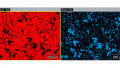
Solder degradation is a typical failure mechanism in power modules and leads to an increased Rth. For this reason, the entire power stack is embedded in a mold compound that stabilizes the soldered stack and thus makes it extremely reliable against thermal cycles. The mold compound is also used to form a durable second level package. Figure 4 shows the quality of the solder joint before and after more than 900.000 active thermal cycles of DT 70°C (at medium temperature Tm = 100°C). After 900k cycles, first signs of beginning degradation
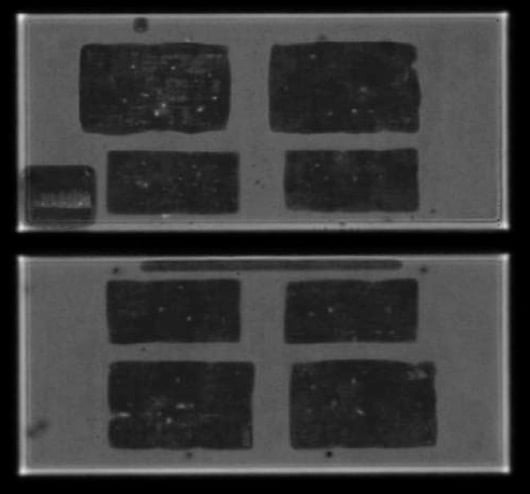
Figure 4: Back side solder quality before (a) and after (b) >900.000 active cycles (DT 70°C, Tm=100°C). First signs of degradation visible underneath IGBT (white arrow)
After more than 1.1 million active cycles, the quality of the solder joints between chip, copper substrate and clips is still very good:

Figure 5: Solder joint quality after >1.1 million active thermal cycles.
Similar observations were made with passive thermal cycles. Even after 2000 passive cycles -40°C to +150°C, no solder degradation could be detected.
Figure 6 shows a lifetime model calculated from experimental validation data based on the LESIT model [1]. For comparison reasons, the figure says the typical lifetime model for gel-filled case type power modules [2]. The significant improvement is obvious. Even with a medium temperature T of 130°C, the lifetime of the molded module cantly higher than for case type module.
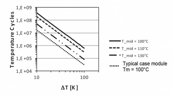
Figure 6: Lifetime calculation for power module MH6560C (Source: Bosch)
Optimized thermal resistance
Compared to alumina substrate based power modules, the thermal path was improved significantly. The copper substrate acts as a heat comparison to standard power modules with Al2O3 DBC, the thermal resistance Rth was improved by about 30% and Zth, relevant for short spreader before the heat passes the thin insulation layer, followed by another thin copper layer and further thermal barriers outside of the power module, like thermal grease and the water-cooled plate. In current pulses was improved by even 70%. The extremely low Rth,jc of 0,06 K/W allows for perfect thermal stacks down to the cooling liquid.
Application support
In order to evaluate the performance of the power module MH6560C in customer specific use cases prior to design in, a complete application kit is available which includes the driver boards for 3 half-bridge power modules, a cooling plate as well as a DC link capacitor. Additionally, driver boards for half-bridge modules are available, which allow testing different building block configurations, for example in motor integrated inverter designs.
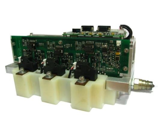
Figure 7: Application kit for the evaluation of MH6560C
Summary
Application specific key parameters were successfully derived from market. All influencing parameters were adjusted for best performance. The combination of matching materials, low-loss power semiconductors, a module architecture with low stray inductance and a thermally improved stack resulted in a power module with best-in-class power density and extremely high reliability.
Bosch intends to continue the design of highly reliable automotive power modules and is now preparing for the introduction of wide band gap materials into power modules. First test vehicles equipped with SiC power modules are under evaluation.
About Robert Bosch
Robert Bosch GmbH is a German multinational engineering and technology company headquartered in Gerlingen, near Stuttgart, Germany. The company was founded by Robert Bosch in Stuttgart in 1886. Bosch is 92% owned by Robert Bosch Stiftung, a charitable institution.
References
- M. Held, P.Jacob, G. Nicoletti, P. Scacco, M. H. Poech, Fast power cycling test for IGBT modules in traction application, Proc. International Conference on Power Electronics and Drives Systems, 1997; 1; pp. 425-430
- R. Amro, J. Lutz, Power Cycling with High Temperature Swing of Discrete Components based on Different Technologies, Proc. of IEEE Power Electronics Specialists Conference 2004 (PESC04), Aachen, Germany ,2004, pp. 2593-2598
This article originally appeared in the Bodo’s Power Systems magazine.
Related Content