Facebook
 Google
 GitHub
 Linkedin
Silver-free AMB Copper Technology Bonds Highly Reliable Metal Ceramic Substrates
High-power electronics have become one of the fastest growing market segments of the semiconductor industry. Because the power electronic modules used in these applications operate at high voltage and high current density, they must handle high temperatures and harsh conditions. One of the key components for highly reliable power electronic modules is a reliable metal ceramic substrate.
To provide reliable functionality during operation, the substrate materials must provide outstanding electrical, thermal, insulation and mechanical performance. Additionally, they must work with commonly used assembly and interconnection technologies like soldering, sintering, and wire bonding.
Due to cost efficiency, Al2O3-based metal ceramic substrates, i.e. direct copper bonded substrates, are often used for power module manufacturing [1]. However, Al2O3-based ceramic cannot fully leverage the potential of wide bandgap semiconductors. As a result, silicon nitride Si3N4-based metal ceramic substrates are gaining popularity as materials for power module assembly. Si3N4 shows superior mechanical properties combined with high thermal conductivity [2].
Highly reliable Si3N4-based substrates are typically manufactured with active metal brazing (AMB) technology that uses Ag-filled and active metal (i.e. Titanium) containing brazing pastes [3]. The precious metal content in the brazing paste and a slow vacuum brazing process are the major price drivers for AMB substrates. Heraeus Electronics, however, has developed a design-to-cost, highly reliable Ag-free thick film copper bonding (Condura Ultra®) technology for joining nitride-based ceramics with Cu foils. The paste eliminates the use of an expensive vacuum-based brazing technology. But how does TCFB perform compared to the industry-benchmark AMB substrate?

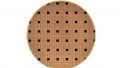
Figure 1. Typical TFCB® microstructure measured by SEM. Image used courtesy of Bodo’s Power Systems
To compare the performance of Condura Ultra to AMB, various reliability and application-related tests such as thermal shock (-65°C/+150°C), peel strength, and high-temperature storage (175°C, 1000 hours) were conducted. Results of the experiments follow.
Phase Formation
The phase formation and bonding mechanism of Condura Ultra technology on Si3N4 ceramics were characterized by scanning electron microscopy (SEM) as shown in Figure 1. The actual bonding mechanism is based on the reaction between the active metal (Titanium) and the Si3N4 ceramic, forming a stable TiN layer. Because there is no silver in the Condura Ultra system, typical Ag- and Curich phases are eliminated, which are known from the standard AMB technology as using high Ag-containing brazing filler metal pastes. Nevertheless, the bonding mechanism towards the Si3N4 ceramic via a TiN reaction layer is similar.
Thermal Shock Performance
Si3N4-based AMB substrates meet the highest thermal shock test (TST) performance requirements because of the ceramic’s mechanical robustness. To assess resistance vs. thermomechanical stress of Condura Ultra on Si3N4 ceramics, thermal shock tests were performed using an internal test layout (30.6x29 mm2 with 0.5 mm Cu on 0.32 mm ceramic) as shown in Figure 2. The status of the Condura Ultra substrates before testing was characterized by scanning acoustic microscopy (SAM) and is shown on the left of Figure 2. The red color indicates an etched isolation groove that is part of the used test layout. In case of delamination between copper and braze metal/ceramic due to thermal shock, the red-colored isolation groove will broaden in the SAM picture. The integrity of the substrates was reassessed by SAM after 3000 and 5000 cycles of thermal shock. The results are shown in the center and right of Figure 2 and illustrate no major broadening of the isolation grooves between the initial status of the Condura Ultra and the cycled Condura Ultra, proving that no delamination between the ceramic and the braze metal occurred. This indicates that the Condura Ultra technology can fully leverage the mechanical robustness of the Si3N4 ceramics, the same as AMB technology.

(A) 0 cycles. Image used courtesy of Bodo’s Power Systems

(B) 3000 cycles. Image used courtesy of Bodo’s Power Systems

(C) 5000 cycles. Image used courtesy of Bodo’s Power Systems
Figure 2. SAM pictures of 20 individual TFCB® test layouts before and after thermal shock tests. The test conditions and further details are mentioned in the text. No major degradation is visible after 5000 cycles.
Copper Peel Strength
The copper peel strength characterizes the adhesion strength of the Cu foil to the ceramic. A simple peel test is used in which a Cu peel strip (10 mm wide x 0.3 mm thick) is brazed onto a piece of 0.32 mm thick Si3N4 ceramic using the Condura Ultra technology. The Cu is peeled off and the force is measured. Figure 3 shows an example of a peel test sample post-peel. The peel strength of this sample was 105 N/cm on average. The peel strength strongly depends on the substrate type and technology being tested.

Figure 3. Peel test sample after peel test. A dark color remains on the peel strip and the substrate, indicating that Si3N4 has been pulled out. The small rectangle indicates the position for the EDS mapping seen in Figure 4. Image used courtesy of Bodo’s Power Systems
Closer inspection of the failure mode of the peel sample can provide valuable information about the bonding quality. Figure 3 shows the peeled-off Cu strip and the remaining substrate counterpart after the peel test (right side). A dark color on the peel strip and the counterpart is visible, indicating pulling out Si3N4 particles from the ceramic substrate. This failure mode is also often observed for Si3N4 AMB substrates. However, there is no failure within the reaction zone of the Condura Ultra substrate. This is proven by EDS phase mapping (Figure 4) that shows most of the remaining material on the peel strip originates from the Si3N4 ceramic and not from the braze metal, indicating the strong bonding mechanism achieved by the Condura Ultra process.

Figure 4. EDS phase mapping of the peeled strip from above. Red color indicates Si3N4 phase, blue color indicates phases from the braze metal. Image used courtesy of Bodo’s Power Systems
Thermal Resistance
The thermal resistance Rth of the metal ceramic substrate is an important factor for the design of the power module. A lower thermal resistance enables a higher power density, reducing chip size. Major contributors to the Rth are Cu and ceramic thickness and type. Condura Ultra interface formation is different than AMB; therefore, it is required to rule out any potential Rth contribution from the braze metal or reaction zone itself.

Figure 5. Cumulative structure functions of AMB and TFCB substrates before HTS. “S” shows the region of the system under test. Image used courtesy of Bodo’s Power Systems
The transient dual interface method was used to assess the thermal resistance of the metal ceramic substrates. Diodes were sintered onto both AMB and Condura Ultra substrates, and the cumulative structure function was calculated from cooling curve measurements after heating the assembly by powering the diode with 40 A. The Rth of the system was then assessed by detecting the point of divergence of two structure functions measured under different boundary conditions, i.e. the assembly was connected by two different thermal interface materials (TIM) – graphite foil and thermal grease – to the cooling system. The resulting structure functions are shown in Figure 5. The point of divergence is similar for both substrate types, demonstrating that there is no difference in thermal performance between AMB substrates and Condura Ultra substrates in the initial status. Afterward, the Condura Ultra substrates were aged in a high-temperature storage (HTS) test for 1000 hours at 175°C to stress the braze metal and prove that the brazing filler metal system is stable. No difference was observed between the initial status and the aged substrate after HTS, showing that the alloy system displays no degradation and consistent values after 1000 hours of aging at 175°C.
Thermal Resistance Simulation
A thermal simulation was performed to assess the influence of thermal conductivity and the thickness of the braze metal layers in the substrate on its total thermal resistance. A Finite Element Method (FEM) was applied to include heat spreading and other geometrical effects. A simplified geometry of a typical chip substrate setup was simulated, including the substrate itself, the braze metal layers on each side of the ceramic/Cu-interfaces, and a silicon chip with a sintered silver die attached (Figure 6). In the simulation, the chip is heated by a constant power of 200 W in its volume for 30 s while the bottom of the substrate is kept at a constant temperature of 25°C.

Figure 6. Layout used for FEM simulation. Image used courtesy of Bodo’s Power Systems
To assess the impact of thermal conductivity and braze metal layer thickness on thermal performance of the Condura Ultra, both parameters were varied and Rth of the chip was tracked as a basic result. The Rth was calculated based on the simulated maximum chip temperature change dTJ and the applied power. Typically, the region close to the chip is heated up the most while regions further away do not show a significant temperature change (Figure 7).

Figure 7. Typical temperature distribution of the TFCB-Chip assembly without TIM in a steady state. Image used courtesy of Bodo’s Power Systems
As a next step, a numerical Design of Experiments (DoE) was conducted. The goal was to identify which of the varied parameters (thermal conductivity and thickness of the braze metal layers) had the highest impact on the Rth of the substrate. For this DoE, an OPTISLANG program created 30 simulations distributed across the total design space as defined by the parameter’s boundaries. Having calculated these results and determined their Rth, a reduced order model was created that allows for a ranking of the influence of the input parameters (thermal conductivity and thickness) on the result (thermal resistance). The intervals for the parameters used for simulation are shown in the table:

Figure 8. DoE output of FEM simulation showing the influence of thickness of braze metal layer and thermal conductivity of braze metal layer on the thermal resistance. Image used courtesy of Bodo’s Power Systems
| Min | Max | |
| Thickness of the braze metal layer (µm) | 20 | 60 |
| Thermal conductivity of braze metal (W/mK) | 51 | 140 |
Table 1. Overview of properties used for FEM simulation.
The thermal conductivity of the braze metal layer is defined by its composition, which is approximated by a bronze composition CuSnx. [7]. Typical variations of the braze metal layer thicknesses are on the order of 20 to 60 µm and were estimated by cross sections of samples and subsequent secondary electron microscopy analysis.
The correlation between the braze metal layer's thermal conductivity, the braze metal layer's thickness and the corresponding thermal resistance can be observed in the surface plot in Figure 8. The main influencing factor is the thermal conductivity of the braze metal layer. The strongest change of the Rth is observed in the region towards lower thermal conductivities while the influence is reduced for higher values. The Rth values extracted from Figure 8 vary between 0.088 to 0.104 K/W using the input from the table. Comparing this theoretical possible range with the measurement results of (0.13 ± 0.03) K/W shows that experimental and simulated values are in agreement. It can be stated that an overall thermal understanding of the Condura Ultra substrate was accomplished.
The performance of Heraeus Electronics’ Condura Ultra technology was demonstrated by thermal shock, peel strength, partial discharge, thermal measurements and thermal simulations. The investigations demonstrate that the Condura Ultra technology enables cost-efficient but highly reliable metal ceramic substrate manufacturing using Ag-free Condura Ultra paste and a non-vacuum-based brazing process.
André Schwöbel, Benjamin Fabian, Daniel Schnee, Miriam Rauer, Anton Miric, Stefan Gunst of Heraeus Deutschland GmbH & Co. KG all contributed to this article which originally appeared in Bodo’s Power Systems magazine.