Facebook
 Google
 GitHub
 Linkedin
High-Frequency 100 V GaN Motor Drives Push LV Motion Control to the Next Level
100 V GaN motor drives enable high-frequency switching up to 100 kHz, delivering greater efficiency and power density, and lower noise than silicon designs. Two eval boards facilitate the design process.
This article is published by EEPower as part of an exclusive digital content partnership with Bodo’s Power Systems.
Article co-authored by EPC's Marco Palma.
Rapid growth in industrial automation, collaborative robots, autonomous mobile robots (AMRs), drones, and precision servo systems is driving the need for a new generation of low-voltage motor drives to deliver higher efficiency, greater power density, and improved dynamic performance. In the past, silicon MOSFETs were the most common switching technology for this voltage range, but nowadays, gallium nitride (GaN) power devices enable inverter architectures that can operate at much higher switching frequencies, improving motor efficiency without the efficiency penalties traditionally associated with silicon.

Image used courtesy of Freepik
Motor drive design requirements are different from data center power converters, as they must simultaneously optimize several performance parameters. In addition to efficiency, design optimization must also account for low torque ripple, low acoustic noise, high current-loop bandwidth, low electromagnetic interference (EMI), complex thermal management, and overall reduced system size. Recent 100 V GaN power stages show the possibility of simultaneously meeting these objectives by carefully optimizing the power devices as well as the surrounding system architecture.
This evolution is exemplified by evaluation platforms like the EPC91124 and EPC91125. Based on the latest generation of 100 V enhancement-mode GaN FETs, these three-phase BLDC inverter platforms run from 18 V to 80 V, allow PWM frequencies up to 100 kHz (150 kHz maximum), and offer continuous phase currents of 30 to 35 ARMs depending on the power stage selected. Rather than just power boards, they are a small development platform for evaluating high-performance motor control, integrating gate drivers, sensing circuitry, housekeeping power supplies, and controller interfaces.
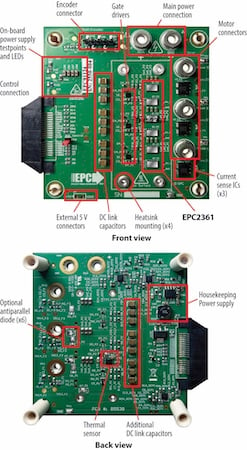
Figure 1. Photo overview of the EPC91124 evaluation board highlighting the main sections. Image used courtesy of Bodo’s Power Systems [PDF]
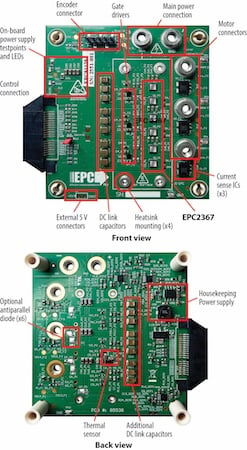
Figure 2. Photo overview of the EPC91125 evaluation board highlighting the main sections. Image used courtesy of Bodo’s Power Systems [PDF]
Moving Beyond the 20 kHz Barrier
Most industrial motor drives continue to operate at switching frequencies between 10 and 20 kHz because switching losses increase rapidly in silicon MOSFETs as frequency rises. Although this operating range is well established, it imposes several compromises. Larger magnetic components and DC-link electrolytic capacitors are required, current ripple increases, control bandwidth is limited, and audible motor noise often remains within the human hearing range.
GaN devices substantially change this design tradeoff. Thanks to their extremely low gate charge and output capacitance, 100 V eGaN FETs enable efficient operation at PWM frequencies around 100 kHz, allowing designers to reduce passive component size while improving current regulation and transient response. Higher switching frequencies improve the motor efficiency by reducing the phase-current ripple, lowering torque ripple and acoustic emissions—important characteristics in collaborative robots, precision servo drives, medical equipment, and high-speed industrial automation. GaN allows designers to improve overall system performance, increasing efficiency while simultaneously reducing inverter size.
Optimizing Switching Speed for Motor Drives
One of the most prevalent misconceptions in GaN technology is that switching transitions should always be as fast as possible. Indeed, controlled switching speeds (dv/dt less than 10 V/ns) are used in motor drive applications with optimal results.
Very fast voltage transitions (dv/dt higher than 50 V/ns) may cause higher common-mode currents through motor cables and bearings, resulting in electromagnetic compatibility problems and potential winding insulation failure resulting in a short circuit. Thus, practical GaN motor drive designs often deliberately reduce the switching voltage slopes.
The inverter platforms discussed here are designed to exhibit dv/dt values below about 10 V/ns, which is a good compromise between efficiency and EMI performance.
Integrated Measurement and Control
As switching frequencies increase, accurate sensing becomes increasingly important. High-bandwidth current feedback is essential for implementing field-oriented control (FOC), and advanced torque-control algorithms.
Both inverter platforms integrate current sensing on all three phases using Hall-effect sensors with a 13.2 mV/A sensitivity, 250 kHz bandwidth, and a measurement range of approximately ±125 A, allowing accurate current reconstruction at elevated switching frequencies. Voltage monitoring is provided for all motor phases and the DC bus through resistor-divider networks with a gain of 29.22 mV/V, while analog outputs remain within the standard 0–3.3 V range used by modern microcontrollers.
The boards integrate three-phase voltage sensing, DC bus voltage monitoring, onboard temperature sensing, regulated 5.2 V and 3.3 V housekeeping power supplies, quadrature encoder / Hall-sensors interface, under-voltage protection, and comprehensive test points for power-stage characterization.
The controller logic interface accepts standard 3.3 V PWM input signals, features approximately 50 ns propagation delay, and supports minimum input pulse widths of 120 ns, making it suitable for high-frequency digital motor-control implementations.
An additional advantage is compatibility with several widely used controller ecosystems, including Microchip dsPIC, Texas Instruments C2000, STMicroelectronics STM32, and Renesas RAx platforms, allowing engineers to evaluate identical power hardware using different digital control strategies.
Dead-Time Optimization Becomes More Important
Migrating from silicon MOSFETs to GaN does not only mean replacing the switching devices. In conventional Si inverters, relatively long dead times are used to avoid cross-conduction. Long dead times are safe but increase reverse-conduction losses and cause waveform distortion.
GaN devices do not have an intrinsic body diode, enabling the dramatic reduction of dead times as they can conduct reverse current. Values of about 50 ns minimize reverse-conduction losses and improve phase-current quality at the same time.
Interestingly, the inverter platforms have optional antiparallel silicon diodes. These are not required for normal operation of GaN but provide additional protection when designers accidentally evaluate the board with firmware originally designed for silicon MOSFET inverters that employ longer dead times. This design decision highlights one of the practical considerations in GaN adoption: best performance depends on hardware choice as much as on firmware optimization.
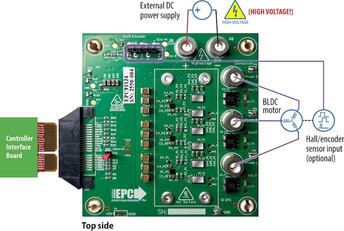
Figure 3. Connection diagram of the EPC91124 configured as a motor drive inverter. Image used courtesy of Bodo’s Power Systems [PDF]
Thermal Performance Under Dynamic Conditions
Rarely are operating conditions of modern robotic or industrial systems described only by continuous current ratings. Motion control applications often face fast-changing load profiles, including acceleration, deceleration, and short torque peaks. The evaluation platforms have been thermally characterized in real operating conditions with a 48 VDC supply, 100 kHz PWM frequency, 50 ns dead time, and at 26 °C ambient temperature.
The higher-current platform is capable of ~30 ARMS continuous operation without a heatsink, and 35 ARMS with passive cooling, with pulsed torque testing showing current peaks of ~65 Apk during short transient events. Similar tests on the second platform confirm good transient capability even with a lower continuous current rating. These results highlight the significance of transient thermal impedance evaluation instead of just steady-state specifications.
The thermal solution is really important. The backside of the GaN device is not electrically isolated; thus, the thermal interface insulating material must simultaneously exhibit excellent thermal conductivity, high dielectric strength, and sufficient mechanical compliance. Proper thermal interface materials enable passive heatsinks to increase continuous current capability without loss of electrical isolation or long-term reliability.
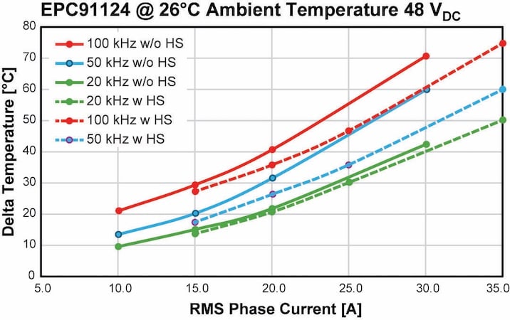
Figure 4. EPC91124 eGaN FET temperatures increase vs. the ambient temperature (26 °C). Measurements were taken at various PWM frequencies. Image used courtesy of Bodo’s Power Systems [PDF]
Selecting the Appropriate Power Stage
Although the two inverter platforms share the same PCB dimensions (79 × 80 mm2), sensing architecture, controller compatibility, and software ecosystem, they target different operating points.
The EPC91124 employs the 3 x 5 mm2 100 V EPC2361 eGaN FET, featuring a typical RDS(on) of 0.75 mΩ. It supports 35 ARMS continuous current and 45 ARMS peak, making it suitable for larger servo motors, industrial actuators, and robotics applications requiring higher torque.
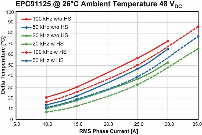
Figure 5. EPC91125 eGaN FET temperatures increase vs. the ambient temperature (26 °C). Measurements were taken at various PWM frequencies. Image used courtesy of Bodo’s Power Systems [PDF]
The EPC91125 mounts the 3.3 x 3.3 mm2 100 V EPC2367, offering a typical RDS(on) of 1.2 mΩ while delivering 30 ARMS continuous and 40 ARMS peak current capability. This provides a cost-performance alternative without changing firmware, controller hardware, or board architecture.
Looking Ahead
In low-voltage motor drives, GaN adoption is no longer just about higher efficiency. Rather, it is a more holistic system-level optimization where the switching devices, sensing, PCB layout, thermal management, and digital control software are designed as one platform.
Table 1. EPC91124 and EPC91125 Parameters.
| Parameter | EPC91124 | EPC91125 |
| GaN device | EPC2361 | EPC2361 |
| Maximum device voltage | 100 V | 100 V |
| Maximum RDS(on) | 0.75 mΩ | 1.2 mΩ |
| Input voltage | 18–80 V | 18–80 V |
| Recommended PWM frequency | 20–100 kHz (150 kHz max.) | 20–100 kHz (150 kHz max.) |
| Continuous phase current | 35 ARMS | 30 ARMS |
| Peak phase current | 45 ARMS | 40 ARMS |
| Current sensor bandwidth | 250 kHz | 250 kHz |
| Current sensor sensitivity | 13.2 mV/A | 13.2 mV/A |
| Voltage sensing gain | 29.22 mV/V | 29.22 mV/V |
| Board dimensions | 79 × 80 mm2 | 79 × 80 mm2 |
These contemporary GaN inverters switch at 100 kHz, which translates to smaller passive components, reduced acoustic noise, improved current regulation, and higher power density, while being compatible with established motor-control ecosystems. Robotics, industrial automation, drones, and intelligent motion systems will continue to require faster dynamic response in increasingly compact form factors, and high-frequency 100 V GaN platforms are expected to become an important reference architecture for the next generation of precision motor-control systems.
This article originally appeared in Bodo’s Power Systems [PDF] magazine and is co-authored by Maurizio Di Paolo Emilio, Marcom Director, and Marco Palma, Vice President of Motor Drive Marketing and System Engineering, Efficient Power Conversion (EPC)