Facebook
 Google
 GitHub
 Linkedin
Dual-Channel 42V 4A Monolithic Synchronous Step-Down Silent Switcher 2 with 62 A Quiescent Current
This article highlights Analog Devices Incorporated LT8650S synchronous Silent Switcher® 2 regulator features a wide input voltage range of 3 V to 42 V.
The LT8650S 42V, dual-channel, 4A synchronous Silent Switcher® 2 regulator features a wide input voltage range of 3V to 42V, ideal for automotive, industrial, and other step-down applications. Its quiescent current is only 6.2µA with the outputs in regulation — a critical feature in automotive environments where always-ON systems can drain the battery even when the car is not running.
In many switching regulator designs, EMI can be a problem if the board layout does not adhere to stringent layout standards. This is not the case with a Silent Switcher 2 design, where automotive EMI standards are easily passed with minimal layout concerns.
7.5 V/4A and 3.3 V/4 A Outputs Have a Fast Transient Response
Figure 1 shows a dual output regulator designed to optimize the transient response. Although the LT8650S includes internal compensation, external compensation is used to minimize the transient response time and output voltage excursions. Switching is at 2MHz, allowing higher loop bandwidth and faster transient response.

Figure 1: 7.5 V/4 A and 3.3 V/4 A outputs feature fast transient response.
Figure 2 shows the output response to a 0A to 4A load step, where VOUT drops less than 100 mV for both the 3.3V and 7.5V outputs. This response is combined with high initial accuracy for a solution that meets tight VOUT tolerance.

Figure 2: 0 A to 4 A transient responses of the circuit in Figure 1 (Burst Mode® operation).
Paralleled Outputs Deliver 9 V/8 A from 24 V While Remaining Cool
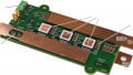
The LT8650S packs two synchronous step-down regulators into a 4 mm × 6 mm package. The two outputs can be easily paralleled for high current as shown by the 72 W output, 24 V input design in Figure 3.

Figure 3: Paralleled outputs deliver 9 V/8 A from a 24 V input while remaining cool
Efficiency at full load is 95%, with the thermal performance of the board shown in Figure 4. Running at room temperature, the hottest part of the IC reaches about 75°C without active cooling. The temperature and efficiency are even better for a 12 V input. When paralleling, it is important to balance the current between the outputs by tying the outputs of error amplifiers together. This can be achieved by connecting VC1 and VC2 together and using external compensation. For applications that require a larger thermal budget, the LT8650H operates with a 150°C junction temperature.

Figure 4: Thermal performance of the circuit in Figure 3.
3.3 V/3 A and 1 V/5 A Running at 2 MHz for an SoC Application
Many system on a chip (SoC) applications require 3.3 V for peripherals and 1 V for the core. Figure 5 shows the LT8650S used in a cascade topology, where the input for the 1 V converter is powered by the 3.3 V output. There are a number of benefits of a cascade configuration overpowering VIN2 from the mains supply, including reduced solution size and constant 2 MHz operation. The 4 A current rating per channel of the LT8650S is based on thermal limitations, but each channel can electrically deliver 6 A if temperature rise is managed with additional cooling. In the solution of Figure 5, the output power of the 1 V channel 2 is low, so it can deliver 5 A.

Figure 5: 3.3 V/3 A and 1 V/5 A circuit running at 2 MHz for an SoC application.
The LT8650S features a wide input range, low quiescent current, and Silent Switcher 2 design. Packing two 4 A synchronous step-down regulators in a 4 mm × 6 mm package reduces part count and solution size while allowing design flexibility for a broad range of applications.
About the Author
Hua (Walker) Bai is an applications engineer at Analog Devices, Inc. He provides technical support for customers in many applications. Before his current position, he worked for Jacobs Vehicle Systems and BEI Technologies. He earned his Ph.D. in electrical engineering from the University of Missouri-Rolla in 2001.
This article originally appeared in the Bodo’s Power Systems magazine.