Facebook
 Google
 GitHub
 Linkedin
Designing a Double-Pulse Test System to Enable Correlation of Dynamic Characteristics
This article discusses important considerations when designing a standard DPT system used to correlate results between multiple test systems.
When evaluating power transistors for your power converter design, it is important to choose the right device for your application. Ideally, datasheets from power semiconductor suppliers would provide consistent results enabling engineers to compare dynamic parameters. For dynamic switching characteristics, this is easier said than done. A standard test system designed to characterize wide-bandgap (WBG) power transistors must keep parasitics small and consistent from system to system. This article discusses important considerations when designing a standard DPT system used to correlate results between multiple test systems.
In principle, a DPT setup is simple as exemplified in Figure 1. Test engineers often simplify the system by replacing the ‘high side’ transistor with a diode. However, after a closer look and considering continuously increasing switching speeds of WBG devices, there are many significant external parasitic components which need to be considered in the system (Figure 2).
_System_To_Enable_Correlation_Of_Dynamic_Characteristics_Figure_1_1.jpg)
Figure 1: Simplified drawing of a DPT setup.
Many external parasitics, especially the three main loops – power loop, gate loop, and DC-link loop – are mostly considered because of the ringing they introduce into the waveforms. We discussed this in great detail in previous articles. However, parasitics also greatly influence the extracted switching parameters. External influences like the inductance shared by the power loop and gate loop LSS, the external gate resistor RG, external gate inductance LG and load inductor parasitics influence a power semiconductor’s switching speed. Additionally, the measured switching energy is influenced by the parasitic capacitance (CInd) of the load inductor and parasitic inductance (LShunt) of the current shunt.
_System_To_Enable_Correlation_Of_Dynamic_Characteristics_Figure_1.jpg)
Figure 2: DPT setup with some significant external parasitics
As discussed in our last article, the shunt bandwidth has a significant influence on switching energy. The parasitic element LShunt leads to a higher measured current peak during turn-on and amplifies all high frequency components of the measured current signal. Characterizing the shunt used for the measurement helps to minimize the influence of LShunt significantly so that it does not have to be considered for comparability when compensated properly.
Power semiconductor datasheets show little information about the DPT systems used for extracting switching parameter. In addition to the test parameters, (e. g. VDS, IDS, VGS) only RG and LInd are typically specified. All these parameters can easily be controlled and changed in the system.
Some datasheets also show the parasitic capacitance (CInd) of the load inductor and total power loop inductance. CInd is an important parameter as it introduces an additional capacitance in parallel to the high side device. During turn-on, this additional capacitance causes higher measured peak currents than the device’s actual reverse recovery current and therefore, increases the switching energy during turn-on. The fixture layout itself can also introduce parasitic capacitances which have a similar effect and are never specified. This effect can be seen in Figure 3 showing turn-on waveforms for VDS and IDS. The measurement with an inductor with higher showed a higher and slightly longer current peak and a delayed falling edge. This leads to an increase in switching energy of 4.5 %. Therefore, it is important to keep both CInd and introduced layout parasitic capacitance minimal.
_System_To_Enable_Correlation_Of_Dynamic_Characteristics_Figure_3.jpg)
Figure 3: Turn-on waveform comparison between two inductors with varying CInd
The total power loop inductance is important as it generates a voltage droop in VDS during the turn-on edge of i D according to: VDS,droop = Lpowerloop · did/dt [1]
This voltage droop becomes significant for fast switching devices with steep current slopes and must be considered for rise-time calculations. It is important to split the power loop inductance into its components LSS and LDS, because they influence the system and measurement results in different ways. LSS contributes to slow down switching speeds as it generates a negative feedback in the gate loop. This slows the output current slope for both turn-on and turn-off transitions. The slower current slope also decreases ringing. In contrast, is the main source of ringing on all signals, (VDS, IDS, VGS) but has virtually no effect on switching speed. It is important to know both LSS and LDS because their influence has opposing effects.
In our last article, we also talked about the influence of time skew of oscilloscope inputs and how to minimize it. Signal skew is important for parameters which rely on two different signals like switching energy and delay time. It is important to consider the probe position for these parameters. Probes can be placed either close to or far from the device under test (DUT), therefore changing the trace length to the probe. This leads to additional skew in the system because of the signal propagation delay. A simple test showed that changing the position of by a few centimeters leads to a change of delay time by 0.5 ns (Figure 4). For slower switching devices with delay times >50 ns this might not be significant. However, new, faster devices show delay times of 5 ns or less which translates into an error of 10 % or more.
_System_To_Enable_Correlation_Of_Dynamic_Characteristics_Figure_4.jpg)
Figure 4: Overlaid turn-on waveforms with different positions for V_GS probe (blue).
Designing DPT systems for comparable results
Currently, semiconductor manufacturers use self-made DPT systems to obtain switching parameters. However, many manufacturers are unable to correlate results from system to system. There are two approaches to get comparable results between multiple systems testing WBG power transistors. For the first approach, manufacturers characterize the parasitics of their DPT system and include them with the test conditions of the specified characteristics. However, it is difficult to know and share information on all parasitics (of layout, inductor, …). It is not easy, or even possible to measure some of these parasitics with high precision. Even if all conditions were known to a high precision and stated, it would still be very hard to quantify the exact influence each of these parasitics had on the result.
Table 1 shows a simplified example illustrating how hard it is to compare measurement results obtained on two different DPT systems. The example shows only some of the test conditions. A realistic table showing all necessary test conditions would have many more parameters listed. Both devices were measured at the same test voltage, current and with the same gate resistor value, but on different DPT systems. Device A clearly shows slower turn-on and higher switching energy compared to device B. However, as we mentioned before, one of the main influences of switching speed and energy is LSS. The test system used to characterize device A has significantly higher LSS compared to device B’s test system. Without simulations and a detailed analysis, it is difficult to compare devices and know which device is faster and consumes less switching energy in the target application.
| Parameters | Device A | Device B |
| V/I | 600V / 20A | 600V / 20A |
| RG | 0 Ω | 0 Ω |
| tdelay_on | 43 ns | 39 ns |
| trise | 34 ns | 32 ns |
| Eon | 563 µJ | 547 µJ |
| LDS | 10 nH | 15 nH |
| LSS | 10 nH | 5 nH |
Table 1: Simplified example showing difficulty of comparable data obtained on different test systems
Because of the difficulties measuring all parasitics and comparing their influence for the obtained measurement result we must look at another approach to achieve our goal.
The second approach to get comparable results is to keep the DPT parasitics constant, and therefore the need for a standard DPT system. With a well-designed and easy-to-use DPT system keeping the potential human error to a minimum, all parasitics and other influencing factors remain relatively constant. Using such a standard system to obtain device parameters for multiple devices clearly makes comparing devices between vendors a lot easier.
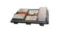
Several issues must be solved to keep parasitics constant, while providing a reliable and flexible system. When considering the DUT interface and gate driver connections, soldering them on a PCB is the most reliable method. However, the engineer loses flexibility. If the engineer wants to change the DUT or the gate resistor, it is necessary to unsolder the old part and solder in the new part. A PCB might be damaged after a couple of device changes and the obtained measurement results are no longer comparable. Specially designed DUT interface boards with tight socket type connectors allow the engineer to easily change transistors (e.g. TO247 packages) without the need for soldering. Therefore, one DUT board can be used for thousands of insertions (Figure 5).
_System_To_Enable_Correlation_Of_Dynamic_Characteristics_Figure_5.jpg)
Figure 5: Standard TO247 test board to gain flexibility in device and gate driver changes
An easy way to gain flexibility for gate drivers is to have a separate, exchangeable board (with different values) which can be plugged on to the same DUT board. The gate driver board allows repeatable and consistent connection to the DUT board.
The ideal scenario for different gate resistors is to have either one gate driver board with switchable resistors or changeable resistors. Introducing switches in the gate loop adds to the parasitic gate inductance and is therefore not preferred. The same is true for having changeable through-hole resistors, as the parasitic inductance is much higher than for surface-mount resistors. Additionally, its handling is too error-prone because resistors can easily be mixed up which leads to faulty test result documentation. The only practical way to properly maintain a small and constant gate and power loop is to have a standard DUT board design with changeable standard gate driver boards. This helps to create comparable results between multiple systems.
When minimizing the parasitic inductance, LDCLink1 and LDCLink2, from the DC-Link capacitor bank to the DUT, a tradeoff is needed. The bulk capacitors are large and unpractical to mount on the DUT board. It is better to put them on a separate main capacitor board to allow more flexibility for different DUT boards (TO247-4, D2PAK-7, etc.). However, this increases LDCLink1 and LDCLink2. Instead, each DUT test board includes decoupling capacitors to keep the power loop as small as possible without losing flexibility. Well-designed decoupling capacitor values minimize the influence of larger LDCLink values.
After making the parasitic inductances in the gate and power loop constant, the biggest remaining influencing factor is the main inductor itself. There are multiple factors to be considered with regards to the inductor.
-
The layout or design of the inductor clearly influences its DC resistance and parasitic capacitance. It is recommended to use the same design for each system to create comparable results.
-
An inductor generates a magnetic field around it. A change of the inductor position in the system might lead to different effects on the magnetic field being induced into the system. Therefore, it is important to have a fixed inductor position.
-
The cable length and cable positioning of the inductor also adds to the parasitics. Longer cables generally lead to higher parasitics. Therefore, a reliable system needs fixed positioning and connection of the inductor. Preferably the user does not have to perform any changes to switch between different inductor values and between a normal DPT or reverse recovery test. This way a maximum comparability between measurements on different systems is achieved.
Both the International Electrotechnical Commission (IEC) and JEDEC have worked on defining tests and characterization standards for decades. With the faster WBG devices, test standards are even more difficult to develop. Users are looking for a way to compare characteristics of different vendor’s parts, so they can choose the best option for their application. But only recently has JEDEC established the JC70 Wide Bandgap Power Electronic Conversion Semiconductor Committee to develop standards for fast, WBG power semiconductors.
Keysight’s PD1500A Dynamic Power Device Analyzer and DoublePulse Tester focuses on consistent and minimal parasitic design, automated testing minimizing human error, ensuring repeatability and comparability between systems. Its modular, but highly integrated approach, ensures the possibility to test devices of various footprints – TO247-3, D2PAK-7 and soon TO247-4 – at different switching speeds with minimal change to the system.
About the Authors
Michael Zimmermann is an R&D Engineer at Keysight Technologies Deutschland GmbH.
Ryo Takeda works as a Solution Architect at Keysight Technologies Incorporated, a company driven to deliver breakthrough solutions and trusted insight in electronic design, test, manufacture, and optimization to help customers accelerate the innovations that connect and secure the world.
Bernhard Holzinger works as a Technical Architect at Keysight Technologies Incorporated, a company driven to deliver breakthrough solutions and trusted insight in electronic design, test, manufacture, and optimization to help customers accelerate the innovations that connect and secure the world.
Mike Hawes is the automotive and energy solutions planning manager at Keysight Technologies. Hawes holds a Master's Degree in Biomedical Engineering from Colorado State University. He also holds a Bachelor's Degree in Electrical Engineering from Washington State University.
This article originally appeared in the Bodo’s Power Systems magazine.