Facebook
 Google
 GitHub
 Linkedin
Customized Current Sensors Enable High Power Density Electric Vehicle Inverters
The demand for high power density converters in EVs requires further integration of sensors within power electronics.
The demand for high power density converters in EVs requires further integration of sensors within power electronics. Danfoss Silicon Power and LEM initiated early 2019 a collaboration with the goal to develop customized and higher integrated current sensing solutions for the DCM™ power modules.
Introduction
A customized version of LEM’s HAH1, an open loop hall effect sensor, was developed. It significantly reduces the assembly footprint compared to previously available solutions and allows a higher integration level within the control infrastructure.
DCM™ automotive traction module platform
Danfoss has introduced the Direct Cooled Molded (DCM™) module technology platform for traction applications in hybrid electric and battery electric vehicles [1,2]. DCM™1000 is prepared to accommodate up to 1000 mm² of semiconductor area with Si or SiC chips from various manufacturers with a blocking voltage of up to 900V and output currents ranging up to 700A. The DCM™1000X family extends the portfolio with utilizing 1200V SiC MOSFETs or Si IGBTs operating at DC-link voltages up to 950V and current ratings up to 660A.

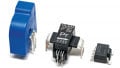
Figure 1: DCM™1000 module with customized HAH1 sensor prototype
The DCM™ utilizes a specific transfer mold package material (Epoxy-Resin) for the power module. In combination with the Danfoss Bond Buffer® (DBB®) technology, the DCM™ platform reaches a superior power cycling performance and lifetime. Applications of the DCM™1000 typically require a current sensor measuring up to ±1100A, including margin for overcurrent detection.
LEM HAH1 current sensor
LEM’s custom design of the HAH1 current sensor for Danfoss’ DCM™ module is part of a range of single-phase products for electronic measurement of DC, AC or pulsed currents in high power automotive applications. HAH1 provides excellent accuracy, very good linearity and low thermal offset.
This custom version of HAH1 has been designed with the objective to minimize the footprint and simplify the assembly process with the controller board using press-fit pins and integrated nuts for easy busbar mounting.

Figure 2: HAH1 prototype characteristic
The first sensor prototypes are constructed for screw connection of the AC-terminal for easy use in evaluation platforms. For series production, variants for welded AC-terminals could be considered.
Enhanced application kit
The DCM™1000 application kit including a reference gate driver, a suitable heatsink for direct liquid cooling and DC cap bank was introduced previously [3,4]. An enhanced version of the application kit was developed with integration of the customized LEM current sensor to demonstrate the benefits of the developed current sensing solution. The power circuit was also updated with a second generation lowinductive DC cap bank.
The kit contains all necessary functions to run as a demonstrator for double pulse and inverter level tests.

Figure 3: Enhanced DCM™1000 application kit incorporating the customized LEM HAH1 current sensor
The signal pins of the current sensor are directly press-fitted into the gate driver PCB which greatly simplifies the interconnection and eliminates expensive and unreliable cable connections.
In our reference design, the current sensor is powered by the highside gate driver channel of each module. The output voltage of the HAH1 sensor is converted on the gate driver board with an insulated ΔΣ-ADC and the digital bitstream is sent to a common 3-phase inverter control board connector. Other implementations without additional signal insulation are also possible depending on the control card architecture.
Mechanical aspects
The housing of the sensor was designed for easy implementation in power converter series production. Features like a press-fit guiding pin, press-fit counter-force elements and bottom-pins for screw counter-torque allow a seamless assembly of a power stack.
The AC-terminal of the DCM™ module was extended by only 8mm, compared to the non-current-sensing version, to fit the HAH1 sensor. Incorporating the current sensor as close to the module enables a very compact inverter design.

Figure 4: Back-side 3D view of customized HAH1 sensor
Power density
Table 1 shows the mechanical and electrical specifications of the application kit available in two voltage classes. The assembly and its geometry were specifically optimized and designed to provide a plug and play SiC-ready solution with high power density, minimized parasitic inductance as well as demonstrating high thermal performance during continuous high frequency operation.
The power density stated in the table refers to real test data with an EV-drive-cycle at max DC-link voltage and current of 650Arms while the junction temperature was monitored and kept below Tjmax with enough safety margin.
| Specification | App kit DCM1000 |
App kit DCM1000x |
| Semiconductor | Si or SiC 750V |
Si or SiC 1200V |
| Dimensions (WxHxD) (mm) | 230x250x95 | 230x250x95 |
| Volume [l] | 5.5 | 5.5 |
| Estimated Dry Weight [kg] | 4.2 | 4.2 |
| Out Power PF=1 m=0.95 [kW] | 295 | 524 |
| Power Density [kW/l] | 54 | 95 |
| Capacitance [uF] | 450 | 276 |
| Commutation Inductance [nH] | 9.3 | 9.3 |
Table 1: Application kit specifications
Hardware under test
The enhanced DCM™1000 application kit was tested in a phaseleg- tester configuration where the two outer phases are connected through inductors to the inner phase which is the device under test.
The following electrical parameters have been used for the test: f_sw = 10kHz, f_fundamental = 50Hz, PF = 1, I_DUT,RMS = 600A.
A LEM LF510-S closed-loop current sensor was used as performance reference. Figure 5 shows the test results with a sinusoidal modulated current. The HAH1 sensor together with the ΔΣ-ADC and decimation filter provides a clean current signal. The Sinc3 filtered ΔΣ-bitstream has an output data-rate of 156kS/s (fclock = 20MHz, OSR = 128).

Figure 5: Test results, comparing HAH1 with LF510-S baseline
AC-terminal temperature
In order to perform IR imaging on the AC-terminal during continuous PWM operation the LEM sensor was removed. Figure 6 shows a thermal image of the application kit (inner phase) after steady state thermal conditions were reached at 650Arms, full DC-link Voltage and 65°C coolant temperature.

Figure 6: Thermal image of AC-terminal
A max temperature of ~115°C (~86°C average) was observed on the AC-terminal. The latter is clearly below the max allowed temperature of the LEM current sensor.
Overcurrent protection
The LEM current sensor comprises an intrinsic delay of approx. 2μs which allows the use of the sensor also for fast overcurrent protection.
Figure 7 shows both the raw analog sensor signal and the digital filtered ΔΣ-ADC signals for an exemplary external short circuit event with fast rising current. A 2nd order 20MHz ΔΣ-ADC in combination with a Sinc2 filter with OSR=32 inserts a group delay of 1.6μs and achieves a resolution of 9½ ENOBs [5] which allows a fast and robust overcurrent detection.

Figure 7: Comparative view between analog and digital signals in a short circuit event
Conclusion and Outlook
Danfoss and LEM collaborated to develop a customized sensor which improves power density, simplifies interconnections and enables further integration of the sensor in the module.
The latest market developments show an increasing trend towards the integration of the current sensing function in the modules. In this context, future developments will increasingly look towards providing an integrated digital output.
References
[1] Bodo’s Power Systems, “Next generation automotive traction power module” (2018); Omid Shajarati, Klaus Olesen, Norbert Apfel, Matthias Beck; Danfoss Silicon Power GmbH
[2] Bodo’s Power Systems, “DCM™1000X - Designed to meet the future SiC demand of electric vehicle drive trains” (2018); Omid Shajarati, Alexander Streibel and Norbert Apfel; Danfoss Silicon Power GmbH.
[3] Bodo’s Power Systems, “DCM™ Powers Electric Vehicles” (2018); Max-Josef Kell, Martin L. Kristensen, Ole Mühlfeld, Omid Shajarati, Robert Roesner, Tim Rettmann; Danfoss Silicon Power GmbH, Germany
[4] PCIM Europe 2019, “A novel application kit design accelerating the performance of Danfoss’ 1.2 kV SiC DCM™1000X for EV drivetrains”, Fabio Carastro, Tim Rettman, Ole Mühlfeld; Danfoss Silicon Power GmbH, Germany
[5] “Signals From Noise: Calculating Delta-Sigma SNRs”; Dave Van Ess, Principal Application Engineer; MTS, Cypress Semiconductor
This article originally appeared in Bodo’s Power Systems magazine.
About the Author
Thomas Zöls worked as a Lead R&D Engineer at Danfoss Silicon Power GmbH Germany.
Fabio Carastro received his Masters degree major in Electrical and Electronics Engineering at University of Palermo,then PhD degree major in Power Electronics and Control at University of Nottingham. He worked as a Senior Electrical Engineer at Danfoss.
Ole Mühlfeld worked as the Application Engineer - Automotive at Danfoss Silicon Power since January 2012. He was promoted and now works as the Director of Application Engineering. He is particularly skilled in the field of power electronics, renewables and automotives. He graduated with his degree in physics from Christian-Albrechts-Univerität zu Kiel in 2007 and stayed on as research staff until 2011.
Jean-François Mercier worked as a Head Automotive Innovation, LEM Switzerland.