Facebook
 Google
 GitHub
 Linkedin
Continuity Tester Operations and Measurement Procedures
A continuity tester is an instrument that checks for a complete path for current to flow.
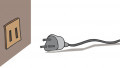
For example, a closed switch that is operating properly has continuity. An open switch does not have continuity (see Figure 1). Some test instruments test for continuity using a continuity test mode.

Figure 1. A continuity checker is a simple test instrument that tests de-energized circuits or components for a complete path for current to flow.
The continuity test mode is commonly used to test components such as switches, fuses, electrical connections, and individual conductors. The test instrument emits an audible response (beeps) when there is a complete path. Indication of a complete path can be used to determine the condition of a component as open or closed. For example, a good fuse should have continuity, whereas a bad fuse does not have continuity.
Continuity Tester Advantages/Disadvantages
One advantage of the continuity test mode of a test instrument is its audible response, which is sometimes more desirable than reading the measurement of resistance. An audible response allows the electrician to concentrate on the testing procedures without looking at the display.
The main disadvantage of using a continuity tester is that continuity testers only indicate continuity by sound on a circuit or component. Continuity testers only operate with circuits that have very low resistance (typically 40 Ω or lower) and will not indicate the actual resistance measurement of the circuit or component being tested.
Continuity Tester Applications
Continuity testers are used to test for a complete flow path in any de-energized low-resistance device. A continuity tester is a common test tool to use when testing single-pole, 3-way, and 4-way switches (see Figure 2). For example, a 3-way switch has one terminal that is the "common" terminal. Depending upon the manufacturer, the common terminal can be located in any position on a 3-way switch. The common terminal is often identified on a 3-way switch by a different color. On specialty switches, such as automobile switches, the common terminal is not identified. Continuity testers are used to determine the common terminal and proper switch operation.

Figure 2. Single-pole switches (SPST) have continuity (buzzing) when closed (ON) and no continuity (no buzzing) when open (OFF).
Warning
A continuity tester must only be used on de-energized circuits or components. Any voltage applied to a continuity tester causes damage to the test instrument and/or harm to the electrician. Always test a circuit for voltage before taking a continuity test.
Continuity Tester Measurement Procedures
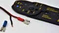
Continuity is tested with a test instrument set on the continuity test mode (see Figure 3). Before taking any continuity measurements using a continuity tester, ensure the meter is designed to take measurements on the circuit being tested. For all measuring precautions, restrictions, and procedures, consult the test instrument's operating manual. Always wear required personal protective equipment and follow all safety rules when taking the measurement.

Figure 3. The polarity of the test leads during a continuity test is arbitrary. Image Courtesy: AgradeTools
To take continuity measurements with a continuity tester, apply the following procedures:
1. Set the continuity tester function switch to continuity test mode as required. Most test instruments have the continuity test mode and resistance mode sharing the same function switch position.
2. Connect the test leads across the component to be tested after the circuit has been de-energized. The test leads are positioned arbitrarily.
3. When there is a complete path (continuity), the continuity tester beeps. When there is no continuity (open circuit), the continuity tester does not beep.
4. After completing all continuity tests, remove the continuity tester from the circuit or component being tested and turn the instrument OFF to prevent battery drain.
Technical Tip
PC board trace continuity testers test the paths of traces by touching the tips of the tester to the components on the circuit board. An audible beep verifies the continuity of a specific circuit. Trace continuity testers use a low voltage that will not bias semiconductor devices into conduction or harm any sensitive components on a PC board.
Related Content