Facebook
 Google
 GitHub
 Linkedin
NEC Basics: Connections and Continuity of Equipment Grounding Conductors in Receptacles and Boxes
Learn how to connect equipment grounding conductors to receptacles and keep their continuity in boxes.
Connecting the receptacle grounding terminal to the metal box ensures an effective ground-fault current path. The basic rule achieves this through an equipment grounding jumper; four exceptions allow other methods. In addition, four installation rules warrant the continuity of the equipment grounding conductors in boxes.
Image used courtesy of Pixabay
National Electrical Code Section 250.146 Connecting the Receptacle Grounding Terminal and the Equipment Grounding Conductor
The general rule requires connecting the grounding terminal of a grounding-type receptacle and a metal box joined to an equipment grounding conductor employing an equipment bonding jumper sized per Table 250.122.
Figure 1 shows how this general rule works. Section 250.118(A)(2) permits the use of rigid metal conduit as an equipment grounding conductor.

Figure 1. Connection of the grounding terminal of a grounding-type receptacle to a metal box. Image used courtesy of Lorenzo Mari
Figure 2 shows a typical way to connect the grounding terminal to the box using a listed grounding clip.

Figure 2. Connection of the grounding terminal to a metal box using a listed grounding clip. Image used courtesy of Lorenzo Mari
The following four sections are exceptions to the general rule:
Section 250.146(A) Surface-Mounted Box
Under some conditions, this section omits the requirement for an equipment bonding jumper between a surface-mounted box and the receptacle grounding terminal – if the direct contact between the device yoke or strap and the metal box provides an effective ground-fault current path.
Figure 3 shows screws securing the receptacle yoke to the surface-mounted metal box with direct metal-to-metal contact.

Figure 3. Screws ensure metal-to-metal contact. Image used courtesy of Lorenzo Mari
Eliminate a minimum of one insulating washer from receptacles to ensure metal-to-metal contact.
Cover-mounted receptacles are approved if the box and cover combination is listed to provide continuity by metal-to-metal contact.
A receptacle installed on a listed cover under both of the following conditions is deemed connected to the ground-fault current path:
The receptacle is attached to the metal cover employing at least two permanent fasteners or has a thread-locking, screw- or nut-locking means.
The cover mounting holes are positioned on a flat, non-raised portion of the cover.
Figure 4 shows a cover without flat nonraised corners to attach the mounting screws – it does not qualify for the omission of the equipment bonding jumper.

Figure 4. Cover without flat, non-raised corners. Image used courtesy of Lorenzo Mari
Figure 5 shows a cover permitted to be the receptacle grounding, and bonding means – there is no need for an equipment grounding jumper.
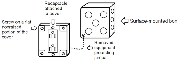
Figure 5. Cover with flat, non-raised corners. Image used courtesy of Lorenzo Mari
Section 250.146(B) Contact Devices or Yokes
Listed self-grounding contact devices or yokes and supporting screws can achieve equipment bonding between the device yoke and flush-type boxes.
Figure 6 shows a receptacle with a spring-type grounding strap for holding the mounting screw. This self-grounding device establishes the grounding connection and avoids using an equipment bonding jumper between the receptacle and the metal flush-type box.

Figure 6. Receptacle yoke listed as self-grounding. Image used courtesy of Lorenzo Mari
Section 250.146(C) Floor Boxes
This section permits floor boxes without an equipment bonding jumper if the assembly is listed as providing ground continuity between the box and the device.
Figure 7 shows a single-gang, rectangular, cast-iron box.
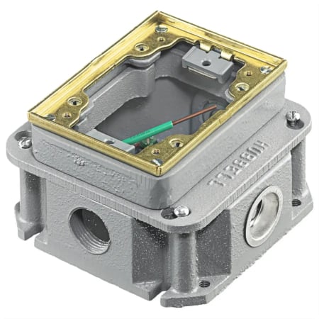
Figure 7. Single-gang floor box. Image used courtesy of Hubbell
Section 250.146(D) Isolated Ground Receptacles
This section permits using a receptacle with a grounding terminal insulated from the frame to reduce the electromagnetic interference that might be coupled through the equipment grounding conductor.
Connect the grounding terminal to an insulated equipment grounding conductor run with the circuit conductors.
The equipment grounding conductor may pass through panelboards without connection to the grounding terminal bar – see Section 408.40, Exception – and through boxes, wireways, or other enclosures without bonding.
The equipment grounding conductor must terminate within the building or structure at an equipment grounding conductor terminal of the related service or derived system.
Figure 8 shows the connection of an isolated ground receptacle with an insulated equipment grounding conductor. The metal raceway system is an equipment grounding conductor for the panelboard and outlet box.
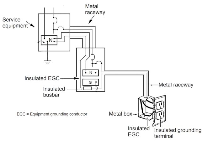
Figure 8. Connection of an isolated ground receptacle. Image used courtesy of Lorenzo Mari
Effective grounding requires the insulated equipment grounding conductor to terminate at the power source for the equipment grounded.
NEC Section 250.148 Continuity of Equipment Grounding Conductors and Attachment in Boxes
Sections 250.148(A) through (D) give rules to install circuit conductors spliced within a box, terminated on equipment inside, or sustained by a box.
An exception establishes the non-requirement of connecting the equipment grounding conductor permitted in Section 250.146(D) to the rest of the equipment grounding conductors or the box.
Section 250.148(A) Connections and Splices
Connect all equipment grounding conductors spliced or terminated within the box. The connections must comply with sections 110.14(B) and 250.8, although no insulation is required.
Employ splicing devices identified for the use or utilize bracing, welding, or soldering with a fusible metal or alloy, per Section 110.14(B).
Section 250.8 lists the permitted and not permitted methods to connect grounding and bonding equipment.
Figure 9 shows wire connectors to connect and insulate two or more copper wires within a box in a pigtail application.

Figure 9. Wire connectors. Image used courtesy of 3M
Figure 10 shows a compression connector tap appropriate to solid and stranded copper conductors.

Figure 10. Compression connector tap. Image used courtesy of Panduit
Figure 11 shows a bolt and nut for bonding two copper ground wires.

Figure 11. Bolt and nut for bonding. Image used courtesy of linemen-tools
Section 250.148(B) Equipment grounding Conductor Continuity
Arrange the grounding connexions to avoid interrupting the effective ground-fault current path due to removing or disconnecting a receptacle, luminaire, or other device supplied from the box.
Section 250.148(C) Metal Boxes
Tie the metal box to the equipment grounding conductor with a connection not used for other purposes. Size the equipment grounding conductor and the equipment bonding jumper per Table 250.122 based on the largest overcurrent protection device.
Figure 12 shows a setup complying with sections 250.148(B) and (C). Removing the receptacle will not interrupt the continuity of the equipment grounding conductor, and the metal boxes are connected to the equipment grounding conductor. This arrangement employs two types permitted as equipment grounding conductors per Section 250.118 – a conductor and a metal raceway.

Figure 12. Arrangement complying with sections 250.148(B) and (C). Image used courtesy of Lorenzo Mari
Section 250.148(D) Nonmetallic Boxes
Arrange equipment grounding conductors in a nonmetallic outlet box so a connection can be made to any fitting or device requiring a tie.
Takeaways of Connections and Continuity of Equipment Grounding Conductors in Receptacles and Boxes
- The grounding terminal of a grounding-type receptacle must be connected to a metal box with an equipment grounding conductor using an equipment bonding jumper, with four exceptions:
◦ Surface-mounted box with direct metal-to-metal contact.
◦ Contact devices or yokes are listed as self-grounding.
◦ Floor boxes are listed as providing continuity for ground-fault currents.
◦ Receptacles with an insulated grounding terminal to reduce electromagnetic interference.
- Comply with the following installation rules when splicing circuit conductors inside a box or if they terminate on equipment within or held by a box:
◦ Connect all equipment grounding conductors spliced or terminated inside the box using the listed connectors.
◦ The disconnection or removal of the device from the box must not interrupt the electrical continuity of the equipment grounding conductor.
◦ Connect the metal box and the equipment grounding conductor.
◦ Arrange the equipment grounding conductors in nonmetallic boxes to provide a connection to fittings or devices when needed.
For more on Lorenzo Mari's NEC Basics series, please visit the following articles.
- NEC 2023 Basics: Grounding and Bonding Piping Systems and Exposed Structural Metal
- NEC 2023 Basics: Equipment Grounding Conductors
- NEC 2023 Basics: Identifying Wire-Type Equipment Grounding Conductors
- NEC 2023 Basics: Sizing Equipment Grounding Conductors
- NEC 2023 Basics: Equipment Grounding Conductor Continuity and Connections