Facebook
 Google
 GitHub
 Linkedin
NEC 2023 Basics: Equipment Grounding Conductor Continuity and Connections
Learn about equipment grounding conductor continuity and connections.
A permanent and electrically continuous ground-fault return path must facilitate the operation of the circuit protective devices, protecting people. To achieve this goal, do not interrupt the equipment grounding conductor and connect it to the right place.

Image used courtesy of Pixabay.
National Electrical Code Section 250.124 Equipment Grounding Conductor Continuity
Section 250.124(A) Separable Connections
Separable connectors must provide first-make, last-break of the equipment grounding conductor unless energizing without grounding continuity is not viable.
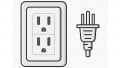
Figure 1 shows a grounding-type receptacle and plug. The grounding prong on the plug is longer than the two blades, providing first-make, last-break operation.

Figure 1. Grounding receptacle and plug. Image used courtesy of Pixabay
Section 250.124(B) Switches
Place an automatic cutout or switch in the equipment grounding conductor only if it disconnects all energy sources simultaneously.
National Electrical Code Section 250.126 Identification of Wiring Device Terminals
Identify the terminal to connect the equipment grounding conductor by one of the following methods:
- A not easily removable terminal screw with a hexagonal head in green color.
- A hexagonal terminal nut, not easily removable, in green color.
- A pressure connector in green color.
If the terminal is not visible, mark the entrance hole for the grounding electrode conductor as follows:
- With the words green, or ground, or
- With the letters G or GR, or
- A grounding symbol, or
- By a distinctive green color.
Mark the area adjacent to the terminal similarly if it is easily removable.
Figure 2 shows a 15 A, 125 V duplex grounding receptacle. Notice the green hexagonal terminal screw.

Figure 2. Duplex grounding receptacle. Image used courtesy of Leviton
Figure 3 shows an example of a symbol to identify the grounding termination point – according to the Informational Note in Section 250.126.

Figure 3. Example of a symbol for the grounding termination point. Image used courtesy of Lorenzo Mari
National Electrical Code Section 250.130 Equipment Grounding Conductor Connections
Connect the equipment grounding conductor at the source of separately derived systems per Section 250.30(A)(1).
Connect the equipment grounding conductor at the service equipment per sections 250.130(A) or (B).
Section 250.130(A) Grounded Systems
Connect the grounded service conductor and the grounding electrode conductor to the equipment grounding conductor. See Figure 4.

Figure 4. Equipment grounding conductor connections in grounded systems. Image used courtesy of Lorenzo Mari
Make the connection on the supply side of the service disconnecting means, i.e., within or ahead of the enclosure.
Switchboards marked as “for use only as service equipment” bring the neutral busbar factory-bonded to the enclosure. Do not use them as distribution switchboards.
Section 250.130(B) Ungrounded Systems
Bond the ground bus and the enclosure to the grounding electrode conductor. See Figure 5.

Figure 5. Equipment grounding conductor connections in ungrounded systems. Image used courtesy of Lorenzo Mari
Section 250.130(C) permits the replacement of non-grounding type receptacles with grounding-type receptacles, snap switches without an equipment grounding terminal with snap switches that do have one, and branch-circuit extensions in existing installations without an equipment grounding conductor in the branch circuit.
Section 250.130(C) Replacement of Nongrounding Receptacle or Snap Switch and Branch Circuit Extensions
Connect the equipment grounding conductor attached to a grounding-type receptacle, a snap switch with an equipment grounding terminal, or a branch-circuit extension to any of the following:
- A reachable place on the grounding electrode system, as explained in 250.50.
- Any reachable place on the grounding electrode conductor.
- The equipment grounding terminal bar inside the box where the branch circuit for the branch circuit extension or receptacle begins.
- An equipment grounding conductor part of another branch circuit starting from the box where the branch circuit for the snap switch, receptacle, or branch circuit begins.
- The grounded service conductor inside the service equipment enclosure in grounded systems.
- The grounding terminal bar inside the service equipment enclosure in ungrounded systems.
Figure 6 shows a branch-circuit extension in an existing installation employing a grounding-type receptacle. Note the equipment grounding conductor connecting the grounding-type receptacle to a metal underground water pipe – a component of the grounding electrode system per Section 250.52(A)(1).
See Section 406.4(D) for specific rules to replace grounding-type and non-grounding-type receptacles.

Figure 6. Branch-circuit extension employing a grounding-type receptacle in an existing installation. Image used courtesy of Lorenzo Mari
National Electrical Code Section 250.132 Short Sections of Raceway or Cable Armor
Follow the rules in Section 250.134 when isolated sections of metal raceway or cable armor require a connection to an equipment grounding conductor.
National Electrical Code Section 250.134 Equipment Fastened in Place or Connected by Permanent Wiring Methods
The non-current-carrying parts of equipment, raceways, and other enclosures, if grounded, must be connected to an equipment grounding conductor by one of the following methods unless joined to the grounded conductor as permitted by sections 250.32, 250.140, and 250.142:
- Connect to one of the equipment grounding conductors admitted by Section 250.118.
- Connect to a wire-type equipment grounding conductor inside the raceway, cable, or run with the circuit conductors.
Figure 7 shows fixed equipment grounded by connection to an equipment grounding conductor of the wire-type run with the circuit conductors.

Figure 7. Equipment grounding conductor to ground a fixed equipment. Image used courtesy of Lorenzo Mari
Figure 8 shows a fixed electric range grounded by connection to an equipment grounding conductor of the wire type contained within a cable Type SE run from a subpanel.
Section 338.10(B) permits a Type SE cable in wiring systems where all circuit conductors are insulated. This section also allows the use of an uninsulated conductor for equipment grounding purposes.
The grounded conductor may be uninsulated as part of a Type SE cable originating from the service equipment in existing installations, as will be seen later.

Figure 8. Equipment grounding conductor of the wire type contained within a cable type SE to ground fixed equipment fed from a sub panel. Image used courtesy of Lorenzo Mari
Figure 9 shows a fixed electric range and a junction box grounded by connection to an equipment grounding conductor of the wire type contained within a cable Type SE run from the service equipment.

Figure 9. Equipment grounding conductor of the wire type contained within a cable type SE to ground fixed equipment fed from the service. Image used courtesy of Lorenzo Mari
National Electrical Code Section 250.136 Equipment Secured to a Metal Rack or Structure
A metal rack or structure grounded by one of the means provided in Section 250.134 shall be permitted to function as the equipment grounding conductor of electrical equipment secured to and in electrical contact with the metal rack or structure.
Figure 10 shows a metal rack, grounded through a rigid metal conduit, acting as the transformer´s equipment grounding conductor.

Figure 10. Metal rack serving as the equipment grounding conductor for a transformer. Image used courtesy of Lorenzo Mari
National Electrical Code Section 250.138 Cord-and-Plug-Connected Equipment
Employ one of the following methods to connect non-current-carrying metal parts of cord-and-plug-connected equipment to an equipment grounding conductor, if required:
Section 250.138(A) Equipment Grounding Conductor
An equipment grounding conductor contained in a cable assembly or flexible cord involving the power supply conductors and terminated in a grounding-type attachment plug with one fixed grounding contact.
Figure 1 shows a grounding-type attachment plug complying with this rule.
Terminate the equipment grounding conductor in the grounding prong on the plug.
The Exception to this section recognizes movable ground pins on grounding-type plug-in ground-fault current interrupters where the voltage is not greater than 150 V.
Section 250.138(B) Separate Flexible Wire or Strap
A separate flexible wire or strap forming part of the equipment, insulated or bare, attached to an equipment grounding conductor and protected against physical damage.
National Electrical Code Section 250.140 Frames of Ranges and Clothes Dryers
Connect the frames of electric ranges, counter-mounted cooking units, wall-mounted ovens, clothes dryers, and junction boxes or outlets that belong to the circuit for these appliances to the equipment grounding conductor per Section 250.140(A) or the grounded conductor per 250.140(B).
Section 250.140(A) Equipment Grounding Conductor
Provide an equipment grounding conductor in the appliance’s circuit and connect it to the frame per Section 250.134 or Section 250.138. See Figures 8 and 9.
Section 250.140(B) Grounded Conductor
When an outlet or junction box of an existing branch-circuit installation does not have an equipment grounding conductor, the frame of the appliance may be connected to the circuit grounded conductor if it meets the following conditions:
- General
The supply circuit is 120/240 V, 3-wire, single-phase, or 208Y/120 V, derived from a 3-phase, 4-wire, wye-connected system.
The grounding contacts of the receptacles furnished as part of the equipment are bonded to the equipment.
- Grounded conductor
Not smaller than size N° 10 AWG copper or N° 8 AWG aluminum or copper-clad aluminum.
Insulated or uninsulated and part of a Type SE cable and the branch circuit originates at the service equipment.
Part of a Type SE cable originating in equipment other than a service. It must be insulated or field-covered within the enclosure to prevent contact of the uninsulated conductor with normally non-current-carrying metal parts.
Figure 11 shows an uninsulated grounded conductor connected to the frame of an appliance. Note that the uninsulated grounded conductor is part of a Type SE cable originating from the service equipment in an existing branch-circuit installation.

Figure 11. An uninsulated grounded conductor connected to the frame of an appliance. Image used courtesy of Lorenzo Mari
Note that this rule applies only to existing branch circuits, not the occupancy, and new installations cannot employ it.
National Electrical Code Section 250.142 Grounding Equipment With The Grounded Circuit Conductor
Section 250.142(A) Supply-Side equipment
It is permitted to connect the non-current-carrying metal parts of raceways, equipment, and other enclosures to a grounded circuit conductor at any of the next positions:
- On the supply side or inside the enclosure of the AC service disconnecting means.
Figure 12 shows the service grounded conductor bonded to supply-side non-current-carrying metal parts, including the disconnecting means enclosure. Note the neutral grounding at the service equipment and utility line.

Figure 12. Supply-side non-current-carrying metal parts bonded to the grounded conductor. Image used courtesy of Lorenzo Mari
This rule also applies to a grounded phase leg.
- On the supply side or inside the box of the main disconnecting means as stipulated in Section 250.32(B)(1) Exception N° 1 for separate buildings.
- On the supply side or inside the box of the overcurrent devices or main disconnecting means of separately derived systems as provided in Section 250.30(A)(1).
Section 250.142(B) Load-Side equipment
Generally, the NEC does not allow equipment grounding using the grounded conductor on the load side of the service disconnecting means, except as permitted in:
- Section 250.30(A)(1) for separately derived AC systems.
- Section 250.32(B) Exception N° 1 at buildings or structures supplied by feeders or branch circuits.
- Part X of Article 250 for systems and circuits of over 1 kV.
Exception N° 1. The frames of ranges, counter-mounted cooking units, wall-mounted ovens, and clothes dryers as provided in Section 250.140.
Exception N° 2. Meter enclosures comply with the following:
- No ground-fault protection was installed.
- Located close to the service disconnecting means.
- Grounded circuit conductors not smaller than specified in Table 250.122 for equipment grounding conductors.
Figure 13 shows a meter arrangement complying with Exception N° 2.

Figure 13. Meter enclosures on the load-side bonded to the grounded conductor. Image used courtesy of Lorenzo Mari
Exception N° 3. Electrode-type boilers operating at over 1 kV and grounded per sections 495.72(E)(1) and 495.74.
Takeaways of Equipment Grounding Conductor Continuity and Connections
- The equipment grounding conductor must be continuous and connected to the right place.
- Detachable connectors must provide first-make, last-break of the equipment grounding conductor unless it is impossible to energize without the ground connection.
- Identify appropriately the terminals where the equipment grounding conductors must be connected.
- Section 250.130 rules the connection of the equipment grounding conductor in separately derived systems and at service equipment for grounded and ungrounded systems. This section also governs the replacement of non-grounding receptacles, snap switches, and branch circuit extensions in existing installations.
- Connect the non-current carrying parts of equipment, raceways, and other enclosures to an equipment grounding conductor following the methods given in Section 250.134.
- Under some circumstances, the NEC permits equipment grounding using the grounded conductor on the load side of the service disconnecting means.
To catch up on Lorenzo Mari’s series on National Electrical Code 2023 Basics: Grounding and Bonding, follow these links:
- NEC 2023 Basics: Grounding and Bonding Piping Systems and Exposed Structural Metal
- NEC 2023 Basics: Equipment Grounding Conductors
- NEC 2023 Basics: Identifying Wire-Type Equipment Grounding Conductors
- NEC 2023 Basics: Sizing Equipment Grounding Conductors
Related Content