Facebook
 Google
 GitHub
 Linkedin
Chip-Embedded Technology Enables High Current Density Power
This article highlights TDK 3D design techniques that can help reduce parasitic losses, and improve thermal performance while also reducing the PCB footprint.
DC-DC power modules in the past 10 years have evolved into new emerging, chip embedded technologies with newly enhanced thermal packaging techniques that allow for higher-density module designs in smaller form factors. Power modules today incorporate: 1) DC-DC converters including FETs and drivers, 2) integrated inductors, 3) passives for Vcc and Boot start up, and 4) in some cases communications for advanced power functionality.
3D design techniques can help reduce parasitic losses, and improve thermal performance while also reducing the PCB footprint. These key factors benefit DC-DC applications requiring compact design and the highest levels of current density and power delivery.
The New Technology
The needed paradigm shift for near future micro-point-of-load power (μPOL™) modules requires leading-edge technologies and a crossfunctional approach:
- Packaging design to address thermal and regulation performance
- Innovative integrated circuit (IC) design for compact regulator design with extreme accuracy
- Paralleled magnetic and discrete component development
- Three dimensional design approach of all on-package components
- Manufacturing technology development for sustainability and reliability

Figure 1: Chip Embedded Power Module Technology
Figure 1 shows an example of the latest developments in chip embedded power module technology. The IC containing the DC-DC regulator circuit is embedded into a thermally enhanced packaging technology called Semiconductor Embedded in SUBstrate (SESUB). The embedded IC die and the SESUB technology includes a patented technology implementation of copper heat sink layers and a 3-dimensional construction of metal and laminate materials, creating reduced thermal resistance paths to the bottom-side of the package substrate. The module substrate, with the embedded die, is 300 μm thick maximum. The SESUB technology eliminates the need for wire bonds which greatly reduces unnecessary parasitic losses while increasing the mechanical package strength. Historically wire bonds are prone to breakage during heavy vibration and drop tests. End product testing has demonstrated that all industry standard mechanical (up to 50G) and thermal stress tests are met utilizing the SESUB technology.
The low profile substrate is then populated on its top mounting surface with an industry leading thin film power inductor, thus yielding an overall thickness of 1.5 mm height. At 1.5 mm, this technology opens the door for low profile DC-DC solutions that enable PCB board layouts to have the power in closer proximity to the load. This is key for upcoming 7 nm ASICs, SoCs, FPGAs and multi-core ARMs covered by height limiting heatsinks under 3 mm.
Examples of 3D Chip Embedded Power Modules
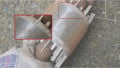
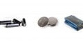
Figure 2 showcases complete high density power modules delivering 15W (FS1406) and 30W (FS1412), at 3.3mm x 3.3mm x 1.5mm height for 6A and 4.9 mm x 5.8 mm x 1.6 mm for 12A, respectively. The 6A device delivers 650 A per cubic inch current density, while the 12A device delivers in excess of 1000 A per cubic inch, with both being two to four times more than current DC-DC power module technologies. These numbers will increase in the near future with the development of 25A to 200A current sharing modules, and at 3 mm to 4 mm height profiles. These will be ideal for high current density core voltages in upcoming artificial intelligent (AI) SoCs and ASICs for small form factor applications.

Figure 2: 3D Chip Embedded Power Modules (compliments of TDK)

Figure 3: Thermal Performance 3D Chip Embedded Power Modules

Figure 4A: Practical Design Using 3D Chip Embedded Power Modules for High Density
Pushing the Barrierof Performance
The new 3D technology comes in both exposed and encapsulated top packaging at highly sustainable production yields and excellent thermal performance, thereby lessening the need for output current derating at higher temperature ambient conditions. It is common for smaller, older power module technology solutions to reduce output current by as much as 40% when the ambient board temperature approaches 60°C to 90 °C, which is rarely the case with the new μPOL 3D technology power modules. Figure 3 lists the measured thermal performance from 3A to 12A at different output voltages and at ambient temperature without airflow convection. The thermal path from the hottest sections of the die through the thermal vias of the SESUB packaging approach proves out the capabilities of the TDK μPOL™ 3D chip embedded technology.
This data confirms that the technology enables an astounding current density of 1 watt per cubic millimeter!
Translating this to practical applications, the FS1406, 6A power module, delivers a full current rating to 80°C at 12V input to 1V output, needing little or no output current derating with zero airflow (operating range -40°C to +125°C) providing the headroom for higher ambient board temperatures. This can help reduce the space and weight of cooling costs in industrial and communication applications.
Putting It All Together for Practical Applications.
Figure 4A showcases the results of a System on Module (SoM) design using a Xilinx Zynq 7 with 3 μPOL 3D power modules. The total DC-DC solution is 6W to 10W power delivery with each module and off-module output capacitors in 49mm2 footprints directly next to the FPGA. The simplicity of the power modules requires minimum output load capacitors, eliminating traditional compensation components and additional voltage divider resistors which further reduces the space and cost. Using PCB thermal vias from 0.5 to 2 ounce of copper and proper board layout delivers excellent thermal performance with only a +13°C rise (without airflow) between the three power modules separated by 6mm. The embedded approach downsizes the SoM card to only 43.7 mm x 17.8 mm, which is up to a 30% reduction of board space over similar solutions.

Figure 4B: Typical PCB Design Footprints – Total Solution
The table in Figure 4B shows the typical design footprints to calculate board spacing advantages using these high current density power modules. They are ideal for placing DC-DC power solutions in the nooks, crannies and voids between and around the FPGAs, ASICs, memory; and under the hoods of heat sinks and/or on the top or bottom sides of mother boards and daughter cards for design flexibility. The power delivery summary: 6A (15W) power delivery with the FS1406 in a 49mm2; and 12A (30W) with the FS1412 in 105 mm2.
Industrial Test and Reliability of Performance
The 3D chip embedded technology and the ability to produce sustainable, long term availability is now realizable at high production yields. Extended reliability tests include: 1) JESD22-A108 for high temperature (up to 125°C) at higher voltages with no failures, 2) JESD22-A104 for the 3000 power cycling test with no failures, and 3) mechanical vibration and shock test. Further information is available on EMI performance such as CISPR-11 performance.
Conclusions
The next generation of new technology power modules are already on-going and are now commercially available. The benefits of the Chip Embedded 3D power modules, or TDK’s μPOL™, are:
- Higher current/power density
- Smaller form factor solutions targeting today’s power challenges
- Low profile (height) packaging for emerging trends of system design
- Improved thermal performance
- More ruggedized package solution
These factors will open new doors for overall higher PCB board density and downsizing, power delivery line loss reductions and weight reduction of the complete power plus thermal solution.
About the Author
Tony Ochoa is the director of marketing engineer, supporting mixed signal analog in both precision and power. He has over 30 years of industry experience, and has worked for Analog Devices, National Semiconductor, Infineon, and several other start-up in the Silicon Valley area. He holds a BSEE and MBA from the University of California. When not working on engineering, you will find him in the waves in Oceanside, California.
This article originally appeared in Bodo's Power Systems Magazine.