Facebook
 Google
 GitHub
 Linkedin
Scalable Power Enables Electrification in Railway System Designs
Learn how DC-DC converters offer a scalable, high-power-density solution for modernizing railway systems, meeting increased power needs, and space constraints.
While the external design of trains often remains virtually unchanged over the years, electrification and the use of new technologies are constantly advancing.
To increase reliability and safety, more and more mechanical components are being replaced by cheaper and less failure-prone electronic devices, monitoring systems allow better control of all functions, and communication with the central control station is constantly being expanded.
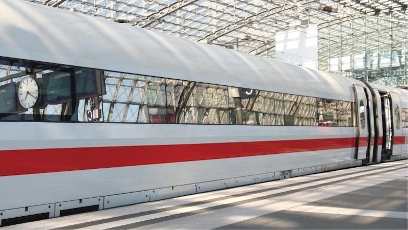
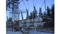
Figure 1. Trains are transitioning from mechanical components to less-failure prone electronic systems.
This development is most seen in the train driver's compartments, where monitors replaced analog meters or warning lights, and fewer switches and levers are used. But even in non-visible areas, an increased number of computers, GPS systems, GSM communication units, and bus systems are used to process the numerous control signals across the complete train.
Space Constraints and Reducing Costs
One of the major challenges in this increasing electrification is the available space. The mechanical design of a train usually cannot be changed, and devices with more features and functionality combined with higher power requirements must fit into the space predetermined by the previous system. For the power supply, this means significantly higher power density and efficiency.
In order to not only save on development costs but also to reduce the number of different power solutions, manufacturers are looking for uniform solutions that can easily be adapted to the various voltage and power requirements of the respective application.
P-Duke's new QBE family of DC-DC converters in the industry-standard quarter-brick format (57.9 x 36.8 mm or 2.28 x 1.45 inches) enables customers to design smaller, more powerful solutions, which can be adopted and scaled to an application by simply exchanging the module and a few external components.
In a specific example, a customer wanted to redesign a central door control unit to integrate more safety features, including ASDO (Automatic Selective Door Opening) using GPS information. Power requirements doubled from 12 V / 35 W to 12 V / 70 W. In addition, the customer wanted to save development costs by using the same power design for a door opener circuit requiring 24 V / 95 W.
The legacy system used a 40 W converter with a footprint of 2 x 1 inches and an efficiency of 86% at 35 W output power. Losses in the converter are:
$$P_{loss} = P_{in} - P_{out} = \frac{P_{out}}{Efficiency} - P_{out} = \frac{35}{0.86} - 35 = 5.7 \text{ W}$$
The heat was spread into the system over the surface of the module and an attached heatsink.
The new QBE75W module from P-DUKE, designed for harsh environmental conditions in rolling stock applications, uses advanced power technologies and achieves an efficiency of 91% at 70 W load with losses of only 6.9 W. Although power was doubled, losses only increased by 20% or 1.2 W. Due to the improved thermal design of this module, most of this heat can be conducted via the baseplate to the metal chassis. This means less thermal stress for all other components.
The QBE family is available with input voltages of 24 Vnom (9 V – 36 V), 48 Vnom (18 V – 75 V), and 110 Vnom (40 V – 160 V), which covers all train voltages, including brownouts and transients.
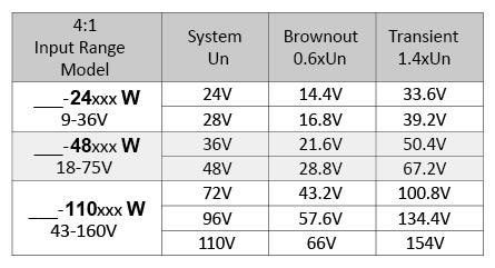
Figure 2. Options in the QBE family of power modules
Why not use one module covering the complete range? The design with an input voltage range of 8:1 or 12:1 makes it difficult to maintain optimal efficiency across the entire input voltage range, as all components must support both high currents at low input voltages and high operating voltages at high input voltages.
Input current is calculated by the formula:
$$I_{in} = \frac{P_{out}}{Efficiency ~ \times ~ V_{in}}$$
The graphic in the Figure 3 below shows the input currents for different working voltages at 91% efficiency and 70W output power.
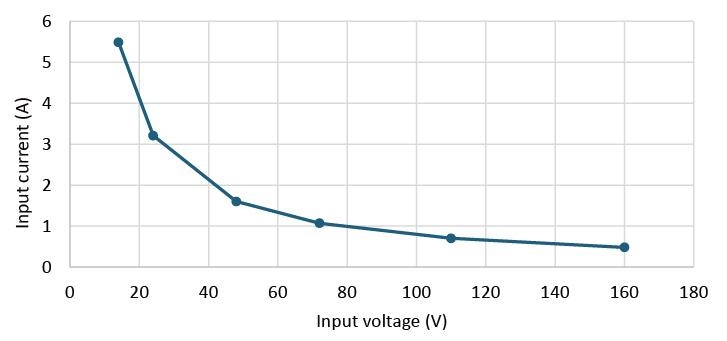
Figure 3. Input currents for different working voltages at 91% efficiency and 70W output power
It is obvious that a “one size fits all” design can’t be ideal when looking for the highest power density and efficiency. Most railway systems are ordered and configured for a specific train application where the supply voltage never changes. All external components, like EMI filters, fuses, or connectors, can be optimized for this specific train, and only the PCB needs to be designed for the high currents and to accommodate all component variations.
Door Opener Example
Like almost all CPU boards today, the one used in the door opener control already has an onboard VRM (voltage regulator module) generating the low supply voltages for the microprocessor from the 12 V bus. All other voltages in the system for memories or interfaces are generated by lower-power DC-DC converters. High isolation barriers are needed for the interfaces, and a P-Duke module with 3000 VDC isolation was selected.
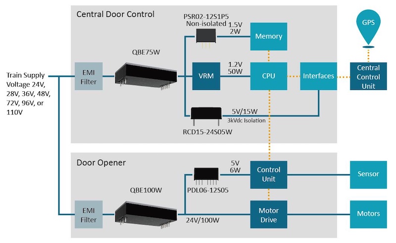
Figure 4. Block diagram of a door control system
For the electric door opener requiring 24 V / 95 W, the customer can switch from a Half Brick module used in the legacy product to the QBE100W module. In the quarter brick format, it is 40% smaller, and the 4% higher efficiency reduces losses by 33%.
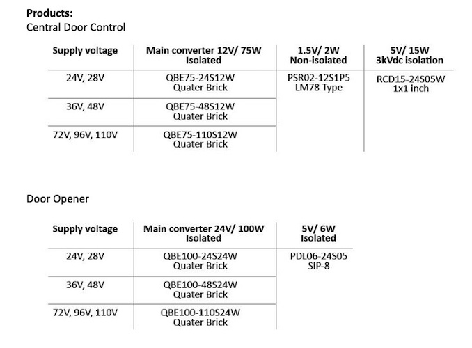
Figure 5. QBE family product selection for the door opener design
The QBE family is available with output voltages from 3.3 V up to 5 4 V. Electrical and EMI behavior and PCB layout are identical for the 75 W and 100 W versions. In this case, the design of the 100 W solution was done in a few hours rather than in weeks or months.
No extensive tests or expensive approvals are needed. And if an application requires a different output voltage? Replacing the module with another part from the same family, adjusting a few external components, and the job is done.
All images used courtesy of P-Duke Technology