Facebook
 Google
 GitHub
 Linkedin
Intro to Magnetic Fields Around a Conductor and a Coil
In this article, learn about the magnetic fields that occur around current-carrying conductors and various shaped coils and how to relate the direction of the fields to the current directions.
When current flows through a conductor or a coil, a magnetic field is set up. This magnetic field increases as the current increases and decreases as the current decreases. The magnetic field's (or magnetic flux's) direction created around the conductor or a coil (solenoid) can be found using the right-hand rule.
Magnetic Field Around a Conductor
When an electric conductor's current flows, a magnetic field is set up around the conductor. This is easily demonstrated by using iron filings, as illustrated in Figure 1(a). A conductor is passed vertically through a hole in a horizontal piece of cardboard. Iron filings are sprinkled on the cardboard, and when the current through the conductor is zero, there is no evidence of a magnetic field. However, when a current flows through the conductor, gentle tapping of the cardboard causes the iron filings to settle in concentric rings around the conductor.
As with other magnetic fields, the field around a current-carrying conductor can also be investigated using magnetic compasses. Figure 1(b) shows the result of placing four compasses on the horizontal cardboard. For a current flowing in a (conventional) direction down through the cardboard, the compass needles point in a clockwise direction around the conductor. Because the direction of magnetic lines of force is defined in terms of the direction in which a free north pole would move, it can be stated that for the conditions illustrated, the magnetic lines of force are in a clockwise direction. When the current direction is reversed so that it flows up through the cardboard, the compass needles reverse and point in a counterclockwise direction.
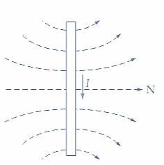
Figures 1(c) and (d) further illustrate the direction of a magnetic field around a current-carrying conductor. The conductor is assumed to be directly opposite the viewer, showing only its cross-sectional area. In Figure 1(c), the current is assumed to flow away from the viewer (i.e., into the page). This is indicated by the +sign, which represents the tail of an arrow. In this case, the magnetic lines of force around the conductor have a clockwise direction. In Figure 1(d), the dot at the center of the conductor cross-section represents the point of an arrow. Therefore, the current flows toward the viewer (i.e., out of the page). The magnetic lines of force now have a counterclockwise direction.
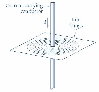
(a) Iron filings form concentric rings around a current-carrying conductor
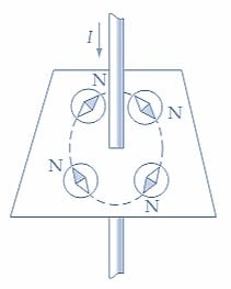
(b) Compasses point in a circle around a current-carrying conductor
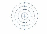
(c) Lines of force are in a clockwise direction around a conductor which is carrying current away from the viewer
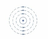
(d) Lines of force are in a counterclockwise direction around a conductor which is carrying current toward the viewer
Figure 1. A magnetic force field in the form of concentric rings can be shown to exist around a current-carrying conductor. Image used courtesy of Amna Ahmad
As shown in Figure 2, two memory aids locate the direction of the magnetic flux around a current-carrying conductor. Figure 2(a) illustrates the right-hand- screw rule, in which the screw is turned clockwise and progressed into a piece of wood. The screw’s horizontal direction corresponds to the direction of the current in a conductor. The circular motion of the screw indicates the magnetic flux direction around the conductor. According to the right-hand rule, shown in Figure 2(b), a right hand is wrapped around a conductor with the thumb pointing toward the current flow. The fingers point toward the magnetic force lines around the conductor.
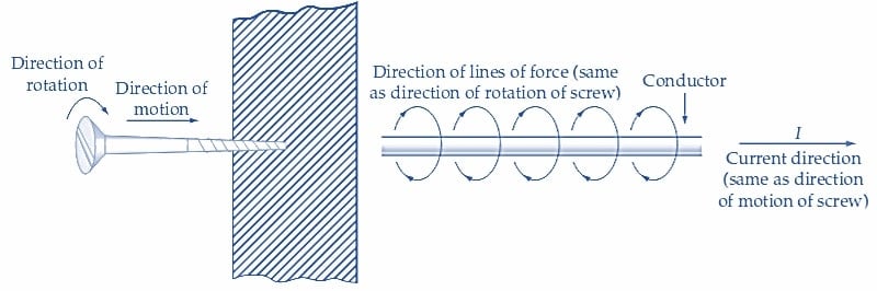
(a) Right-hand-screw rule
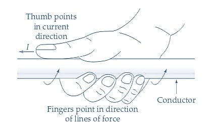
(b) Right-hand rule
Figure 2. The right-hand-screw and right-hand rules determine the direction of the magnetic lines of force around a current-carrying conductor. Image used courtesy of Amna Ahmad
In the case of two current-carrying conductors being brought close together, the fields of the conductors will interact since each conductor has a magnetic field around it. When two conductors carry currents in opposite directions, the effect on the fields is shown in Figure 3(a). The directions of the magnetic fields around the conductors are in opposition, similar to when two like magnetic poles are brought close together. The fields exert a force of repulsion on each other, tending to push the conductors apart. When the adjacent conductors have currents flowing in the same direction [Figures 3(b) and (c)], the magnetic fields assist each other.
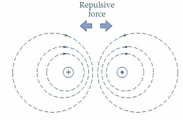
(a) Force of repulsion exists between conductors carrying currents in opposite directions
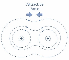
(b) Force of attraction exists between conductors carrying currents in the same direction
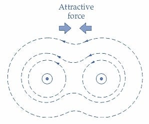
(c) Force of attraction exists
Figure 3. The magnetic field around two parallel current-carrying conductors shows that a force of repulsion occurs when the currents are in opposite directions. When pointed in the same direction, an attractive force exists. Image used courtesy of Amna Ahmad
Because the lines of force are always in tension, they are always trying to find the shortest path. Consequently, the fields exert a force that tends to pull the conductors together, as illustrated.
Magnetic Field Around a Coil
Now consider the effect of passing a current through a one-turn coil of wire. Figures 4(a) and (b) demonstrate that the magnetic flux generated by an electric current passes through the coil’s center. As a result, the one-turn coil behaves like a small magnet and has a magnetic field with distinguishable N and S poles. The coil may have more than one turn, as shown in Figure 4(c). in this instance, the flux produced by each individual current-carrying turn of this coil tends to link up and pass out of one end and back into the other. This kind of coil, referred to as a solenoid, essentially has a magnetic field pattern similar to a bar magnet.
Figure 4(d) illustrates the right-hand rule to determine the direction of flux from a solenoid. By gripping the solenoid with the right hand, the fingers point toward the current flow in the coils, and the thumb points in the direction of flux.
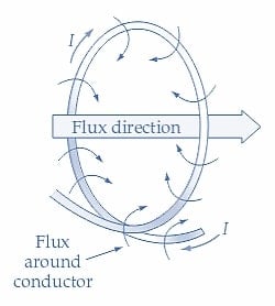
(a) All the flux passes through the coil turn’s center
(b) Side view of coil turn and its flux
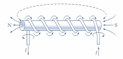
(c) A solenoid establishes a flux like a bar magnet
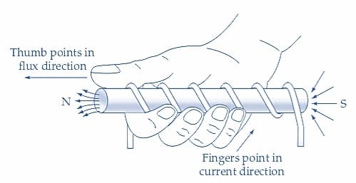
(d) Right-hand rule to determine solenoid flux direction
Figure 4. In current-carrying coils, the magnetic lines of force around the conductors pass through the coil’s center. Image used courtesy of Amna Ahmad
Setting Up a Magnetic Field
When an electric current flows in a conductor or through a coil of wire, a magnetic field is set up, which can be investigated using magnetic compasses. The right-hand rule can determine the direction of the magnetic flux around a current-carrying conductor or from a coil (commonly known as a solenoid).