Facebook
 Google
 GitHub
 Linkedin
An Introduction to Magnetic Components: Inductors
Understanding the how and why of magnetic components helps power engineers with their designs. Here, learn about the history, materials, and uses of the inductor.
Magnetic components have been used in several power electronic devices for decades. They are used for the control, transfer, and conditioning of electric power. Designers are always on the lookout for new materials, topologies, and processes in order to improve performance.
There was a time in history where the design of magnetics was considered more of an art than a science. This is because the design was mostly dependent on trial and error techniques, empirical formulae, and rule-of-thumb considerations. Further, there have been several attempts to standardize the design process to make it more reliable and repeatable.
Read on to learn more about the design of a magnetic component called an inductor, particularly the key concepts involved and design principles.
The History of the Inductor
The design of the inductor was accomplished using trial and error methods like Hanna curves in 1927 [1]. More reliable design techniques like the area-product method and core geometrical constant methods were later introduced.

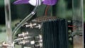
Figure 1. A selection of different inductor types. Image courtesy of FDominec [CC BY-SA 3.0].
To analyze these methods, an equivalent magnetic circuit of the inductor is modeled and the relationship between various components is studied.
The design of inductors is governed by electrical, mechanical, and thermal requirements. In general, the design of any inductor involves the following steps: [2]
- core material selection
- core shape selection
- core size selection
- winding wire selection
In the case of switched-mode power converter systems, inductors typically operate in the linear region. Since the closed-loop dynamics are governed by the values of capacitance and inductance, it is intended that the value of the inductance be small. Also, the value of inductance in the circuit governs the mode of circuit operation. This translates to the design of a large value of inductance to prevent operation in discontinuous conduction mode.
Similarly, in order to ensure the best dynamic performance, inductance should be small at higher loads and vice versa. When all of these are critical requirements for the design and cannot be compromised on, non-linear inductors are employed instead of linear inductors [1]. Figure 2 shows an example of non-linear inductor characteristics.

Figure 2. Sample non-linear inductor characteristics
Inductor Key Components and Concepts
Magnetic wire refers to an enamel-coated wire primarily made of copper and coated with layers of insulating polymer material. Windings are made of a variety of magnetic wire shapes, including circular or square cross-section, rectangular foil, or even Litz wire.
Insulation is used on the surface of bare copper wire to prevent short circuits or breakdowns. A magnetic core is employed to confine and guide the magnetic fields, and the choice of geometry and the magnetic material is based on the requirements of the intended application.
The selection of the core material is governed by:
- operating frequency
- significant harmonics
- relative permeability
- the peak value of magnetic flux density
- the maximum amplitude of the magnetic flux density decided based on the temperature rise limits
- selection between the ferrite material and iron-powdered material based on the design constraints
The selection of the core is governed by the requirements of:
- core size
- core shape
- core volume
- winding window considerations
- air gap
The choice of winding conductor is governed by the requirements on:
- conductor shape
- conductor size
- insulation
- number of layers
- number of turns per layer [2]
Design Procedure and Insights
The design of an inductor is governed by the requirements of a particular application and it can be determined using Faraday’s equation. In the case of resonant circuits, inductance can be determined by using the frequency and quality factor.
In order to use the area-product method, the energy that has to be handled by the inductor core is used to determine the area product value while computing the window factor and crest factor. Then, the winding details — including the cross-section area of the wire required, air gap, the number of turns per layer, etc. — are estimated. A brief check is carried out to validate the calculations of core and winding dimensions based on the area product inequality requirement. Further details, derivations, and equations used for calculation purposes can be found in the literature including references [1] and [2].
Given that the permeability of the core does not remain constant, the design might not provide the exact value of inductance. The fine-tuning to accomplish the same can be done by adjusting the air gap. There are ferrite cores with pre-adjusted air gaps that can be directly used and tuned based on the inductance factor requirement.
It is important to note that, for an inductor, the air gap is incorporated between different kinds of laminations designed during the core assembly and the air gap length depends significantly on the core geometry. The choice of wire size for the windings is also governed by the target copper losses and the allowable resistance value.
Key References
- L. Umanand, S.R. Bhat, “Design of Magnetic Components for Switched Mode Power Converters”, Wiley Eastern Limited.
- Marian K. Kazimierczuk, “High-Frequency Magnetic Components”, John Wiley and Sons, Ltd.