Facebook
 Google
 GitHub
 Linkedin
An Evolution in Isolated Current Sensing for Automotive Design
As electrification gains momentum, current sensor technology is poised to play a significant role.
This article is published by EEPower as part of an exclusive digital content partnership with Bodo’s Power Systems.
Isolated current sensor technology is becoming increasingly important for vehicle design. Current sensing is already a vital part of automotive design, ranging from simple resistance-based measurement to more advanced sensors developed to analyze the behavior of fuel-injector systems. As electrification gains momentum, current sensor technology is poised to play an even more significant role, adapting to the specific requirements of these new vehicles.
A major design change accompanying the evolution of the electric vehicle is detecting currents accurately in high-voltage subsystems and protecting the advanced controllers that interpret and act on these signals. Current sensors in high-voltage domains are needed in numerous locations, ranging from fast battery charge circuits to heating units.
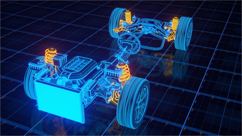
Image used courtesy of Adobe Stock
High-Voltage Current Sensing Applications
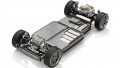
One of the most important targets for accurate current sensing lies in the battery management system (BMS). Batteries are sensitive to overcharging, and the trend toward fast high-voltage charging at 800 V makes this measurement even more critical. By monitoring current information, the BMS can accurately sense battery estimation, detect and diagnose faults, and ensure that charging is completed safely.
In electric vehicle motor control units, feedback provided by changes in current levels can accurately determine real-time power and torque, providing the information needed by the algorithm to determine when best to switch the power transistors that deliver energy to the motor. As the motor and related power transistors will operate at voltages of 400 V or even higher to take advantage of efficiency gains, the current-sensor signal delivered to the controller must be protected against surges and spikes.

Figure 1. Power-factor corrected onboard charger and DC/DC converter modules in a typical EV (NEV WP – Fig 23). Image used courtesy of Bodo’s Power Systems [PDF]
Current sensors play a vital role in the onboard charger (OBC) and the associated power-factor correction (PFC) circuit to ensure that the EV complies with regulations for connecting high-voltage, high-current loads to the public electricity supply. In the OBC, sensors are often needed to measure the current flowing at the AC input as well as within the conversion circuitry and at the output to confirm that the charger is delivering AC power to the rest of the system correctly and that DC power is supplied at the correct level to the battery packs. To ensure the safe operation of the microcontrollers that manage these systems, the current sensors in the high-voltage subsystems need to be isolated.
AC and DC Options
In addition to considering attributes such as accuracy and isolation, another important factor in determining which current-sensor technology to use is whether the circuit uses AC or DC operation. Though the input and output from batteries will be DC-based, motor controllers, electric air conditioning, and similar systems will typically operate on AC.
With DC, shunt-based current sensors, which use high-resistance elements to generate a voltage signal from the current that passes through them, can be employed. These sensors can offer high precision and strong protection from electromagnetic interference. However, their output needs external isolation as, despite their high resistance, they provide a direct path for current from the high-voltage subsystem to the control electronics.
Though magneto-resistive sensors are now beginning to appear, using a similar technology to that used in magnetic memories and hard disk-drive heads, the core technology for sensors used in either AC or DC circuits is the Hall effect. A traditional Hall-effect sensor module wraps a magnetic core around the interface conductor. This core surrounds the conductor except for a small air gap in which the Hall-sensor element sits.
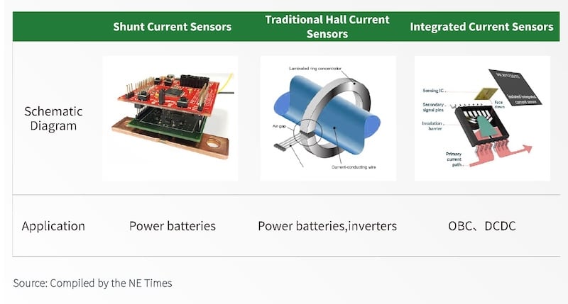
Figure 2. Different types of current sensor (Source: NEV WP - Fig 43). Image used courtesy of Bodo’s Power Systems [PDF]
A current passing through the core creates a magnetic field, generating an electric field. This electric field is detected by a Hall element placed in the air gap, resulting in an output voltage proportional to the field‘s strength. This voltage signal has a linear relationship with the current flowing through the primary conductor. Though the Hall-effect module is isolated from the primary conductor, a design that sees this type of module used widely in electricity distribution systems, it has the disadvantage of a relatively large size. However, it is a design that can safely measure currents as high as 2000 A.
Integrated Hall-Effect Sensors
Integrated-circuit current sensors using the Hall effect have the benefit of being much smaller and easier to deploy on PCBs. This type of Hall sensor does not use a separate magnetic core. Instead, current measurement is performed by sensing the magnetic field generated by the current flowing through a primary conductor that passes through the chip package.
Because of the smaller size of integrated devices and the package constraints, integration implies lower maximum current levels that can be measured than those of module-based sensors. The main reason for this lower limit is the resistance the conductive path through the sensor may impose on the current flow, which leads to self-heating. However, manufacturers have succeeded in limiting this effect.
Integrated Hall-effect current sensors are often suitable for use in AC/DC converters and inverters used in onboard charging systems, heating systems, and some motors. Though their overall isolation performance will be different from a module, because there is an insulating barrier between the primary conductor and the sensing element, the integrated Hall-effect current sensor will meet high isolation requirements.
One potential issue with direct sensing is that strong external magnetic fields can distort the signal, which could be problematic in the complex magnetic environment close to electric motors. One way to solve this problem is to employ two Hall-effect elements differentially. This placement cancels the effect of any common-mode magnetic fields.
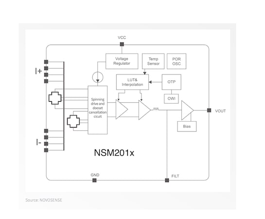
Figure 3. Block diagram showing the use of differential Hall-effect sensing in the NSM201x series (Source: NEV WP - Fig 44). Image used courtesy of Bodo’s Power Systems [PDF]
IC-based Implementation Advantages
The NSM2019 current sensor manufactured by Novosense Microelectronics provides an example of the benefits of an integrated design based on a differential architecture. The product’s novel package design reduces self-heating by providing a primary conductor resistance of just 0.27 Ω, supporting primary current levels as high as 100 A.
Materials choices ensure the relatively small package achieves an operational isolation voltage of at least 1500 V. On top of this, the insulation will survive 10 kV of surge voltage and 13 kA of surge current without additional protective devices. The dielectric withstand voltage reaches as high as 5000 Vrms. The novel package design delivers a comparatively long creepage distance of 8.2 mm. Creepage is an important parameter as it considers changes as the result of aging, such as environmental contamination, that could compromise isolation performance if the distance is inadequate. This combination of properties lets the devices easily meet the voltage and current surge protection requirements of today’s EVs.
The NSM2019 handles the isolation needs of today’s EVs and future model designs and has several convenient features for systems integration. The device supports both fixed and pseudo-differential output modes to improve signal integrity. Furthermore, the circuit is designed to ensure output voltage does not fluctuate with the supply voltage. This approach removes the need to employ a high-precision voltage regulator to supply power to the device, simplifying the bill of materials.
The design of the NSM2019 considers the wide temperature variations that can be encountered in the automotive environment. Using a combination of offline calibration and thermal compensation algorithms, the output maintains high accuracy across the full temperature range of –40 to +150°C.
As vehicle makers continue to exploit the efficiency advantages of employing key subsystems with high-voltage circuitry, the importance of current-sensor technology in ensuring reliability, safety, and performance grows. Manufacturers are meeting this demand by developing sensors with intrinsic designs that guarantee safety and performance.
This article originally appeared in Bodo’s Power Systems [PDF] magazine.