Facebook
 Google
 GitHub
 Linkedin
A Step Forward to Miniaturization for Current Sensing in Power Conversion Systems
This article highlights LEM HMSR current sensor models that include a low-resistance primary conductor, a miniature ferrite, and a proprietary ASIC.
Modern power conversion systems must simultaneously become more efficient, smaller and cheaper than the previous generation. With this in mind, the Swiss company LEM, a global leader in current and voltage sensing, has used its expertise in this field to create a single chip package, the HMSR.
The traditional way to measure current is to use Open Loop Hall effect sensors. The magnetic field created by a current is captured by a magnetic core and measured by a Hall element. More recently, dedicated ASICs helped to increase the overall accuracy of the system using advanced compensation techniques.
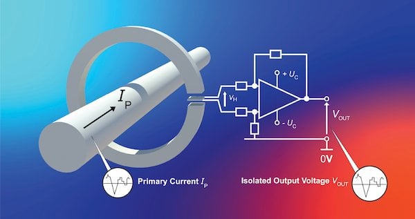
Figure 1: Open Loop technology principle using a traditional Hall effect chip or a dedicated ASIC
LEM first moved into miniaturization with the LTSR product in the previous decade. At that time, the best way to ensure optimum performances was to use Closed Loop Hall effect technology in combination with a special Closed Loop ASIC designed by LEM. The evolution of ASICs technology enabled the development of Open Loop Hall effect sensors that were capable of approaching the level of performance that Closed Loop technology delivered.
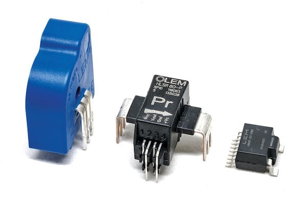
Figure 2: Evolution of the current sensor’s size over the decades
Not only did Open Loop technology make it easier to reduce the size of components but it also brought the cost improvements that the market demanded, thanks to it having a simpler structure and lower power consumption. This decade has seen the development of the HLSR series which not only delivers high performance in terms of offset and drift but also excellent response time – and all in a package small enough for PCBA-type applications with only a few mm height.
LEM has used the extensive know-how and design expertise that it has accumulated over many years to create the HMSR, a state-of-the-art current sensor that satisfies the continuous market requirements of cost reduction, performance improvements, and miniaturization.
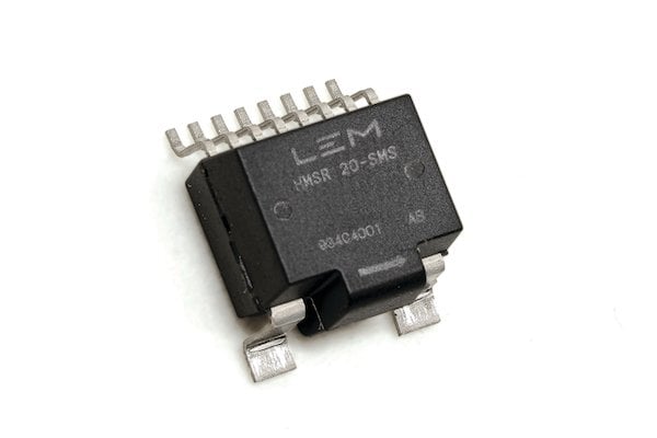
Figure 3: HMSR current sensor
HMSR Models
With this new series, LEM is expanding its miniature, current sensors range for AC and DC isolated current measurement. The new HMSR models are easy to use because they include a low-resistance primary conductor (which minimizes power losses), a miniature ferrite and a proprietary ASIC to allow direct current measurement and consistent insulation performance.
Six Different Nominal Currents
This new product category already includes six different nominal currents — 6A, 8A, 10A, 15A, 20A and 30A — with a measurement span of 2.5 times the nominal current available in a SOIC 16 “like” footprint package. Standard models provide an analog voltage output with different sensitivity levels available, with 5V power supply versions achieving an output voltage of 800 mV @ I PN.
Over-current Detection or OCD
Built-in are two OCD (over current detection) units that separate the control application path to the safety loop. These OCDs are on two dedicated pins — one set internally at 2.93 x I PN as threshold and one externally whose threshold can be adjusted by the user.
HMSR Unique Primary Conductor
However, HMSR sensors should not be seen as a simple Open Loop Hall effect ASIC-based transducers. The HMSR unique primary conductor allows an overload of punctual currents and a high level of insulation. All this is combined with a ferrite-based magnetic circuit to provide excellent immunity against the external inhomogeneous fields found in power electronics applications. This enables the HMSR to be used in environments with high levels of disturbance.
Ferrite for Good Rejection Against External Fields
The ferrite used in the HMSR is also a key factor in achieving a high-frequency bandwidth of 270 kHz (-3dB) and makes it possible to achieve good rejection against external fields.
Dedicated ASIC Designs
These dedicated ASIC designs combine field-proven techniques such as spinning, programmable internal temperature compensation (EEPROM) for improved gain and offset drifts. The result is high levels of accuracy across a range of temperatures, from -40°C to +125°C with a typical value of 0.5 % of I PN (the HMSR 20-SMS model). Power conversion applications such as solar inverter or drives demand high-efficiency levels and these can be reached only if the control loop is accurate.
The accuracy over temperature figures has been greatly improved on the HMSR in comparison to the previous generation of products. The graph below shows the low level of typical overall error across a measured current with the HMSR 20-SMS, as well as very good linearity on a wide temperature range (-40°C to +125°C).
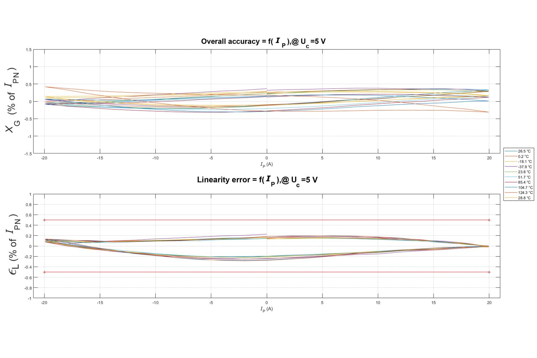
Figure 4: Typical overall accuracy and linearity for HMSR 20-SMS model from -40°C to +125°C)
However, such accuracy is not enough if it isn’t backed by a fast response time. To this end, the deployment of a fast IGBT, like SiC based technology, increases the possibility of working with a faster switching frequency — the HMSR is proven to be ready for such demanding technology with a response time below 2uS (Figure 5).
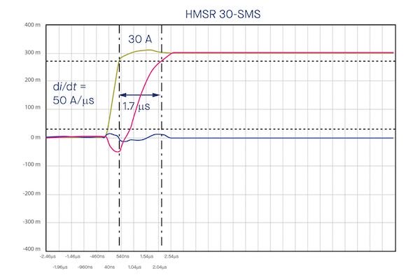
Figure 5: HMSR response time
HMSR Sensors can be Mounted Directly onto a PCB
In multiple applications, HMSR sensors can be mounted directly onto a printed circuit board as SO16 SMD devices, reducing manufacturing costs and providing much-needed space-saving for restricted environments. At just 6mm high, the HMSR offers significant space-saving in applications, making it ideal for placing under the heatsink over intelligent power modules (IPMs) (Figure 6).
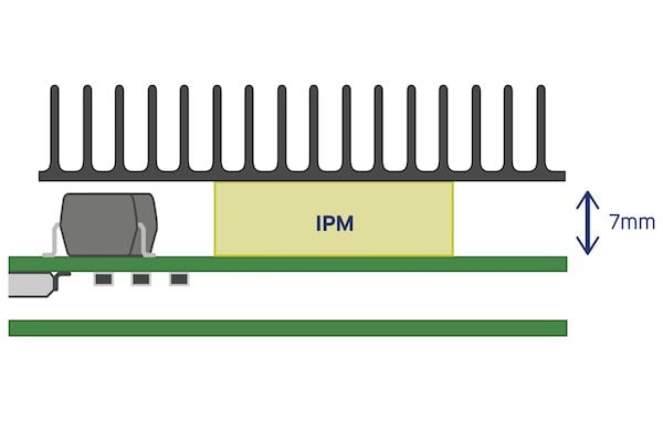
Figure 6: HMSR mounted with IPM
Another area where the HMSR will deliver significant benefits in terms of current measurement is in solar applications.
HMSR benefits for MPPT
In particular, the maximum power point tracker (MPPT), an important asset in solar energy conversion, is a collection of components that maximize the power generated from a photovoltaic (PV) panel. It does this by regulating current and voltage depending on temperature, sunshine and total resistance of the system. The control system permanently analyses the system output after injecting a small perturbation (using the perturb and observe method).
The MPPT then analyses the resulting power (by sensing voltage and current) and deducts the parameter to change in order to reach the MPP (maximum power point). The MPPT then changes the pulse width modulation (PWM) to adapt the voltage of the DC/DC converter.
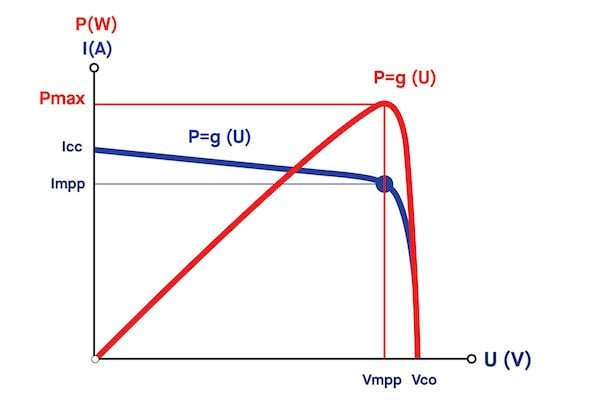
Figure 7: Maximum Power Point
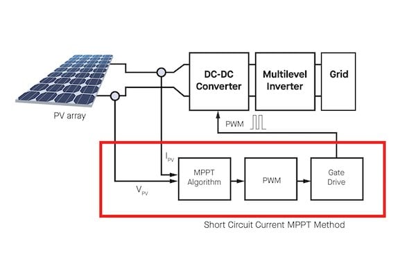
Figure 8: MPPT architecture
Accuracy and Lower Noise
The greater the accuracy and lower the noise, the better the performance from the MPPT will be. Using LEM’s state-of-the-art ASIC, the HMSR provides a highly accurate and very low-noise signal which allows the system to operate to its optimal level.
What’s more, string current monitoring makes it possible to compare several strings and to detect issues such as faulty wiring, dirt on the panels and shadows created by growing trees. Here, the excellent accuracy of the HMSR will enable strings to be compared.
HMSR Ruggedized Design
In addition, the DC/DC converter used in the MPPT uses high-frequency regulation (around 80kHz), creating high dV/dt which is harmful to electronic components. Thanks to its ruggedized design, the HMSR offers significant resistance to such a noisy environment.
This immunity can easily be checked by applying dV/dt through the sensor and observing the output reaction.
The following graphs (figure 9) show the low disturbance created by applying dV/dt through the sensor. The error generated is only 3% of full scale with a recovery time of 3.8uS.
HMSR 20-SMS tested with pulsed voltage of +/- 1000 V at 20kV/uS :
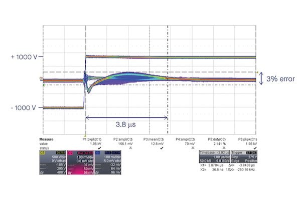
Figure 9: Error generated at the HMSR output after applying dV/dt
Short-circuiting and Overload
The two available built-in OCDs on the HMSR will also protect transistors on the inverter from short-circuiting and overload. This kind of detection and protection is an important feature for multiple applications like HVAC on the DC link or motor drive applications.
Most modern variable-frequency drives (VFDs) incorporate a motor overload algorithm and the OCD function on the HMSR will make detection much easier, preventing the overheating of equipment. Having two distinct OCDs provides the opportunity to monitor overload and short-circuit events separately.
Isolation Requirements
Of course, isolation requirements could be an issue for the adoption of IC packages when it comes to choosing a current sensor. For example, in the solar industry power plants are often used with higher DC voltages, up to 1500V in order to increase the DC/AC power ratios. This dramatically increases the isolation needed for a current converter.
The long internal distance between primary and secondary sides helps to isolate the primary bar with the rest of the IC, giving a very high level of isolation guaranteed at 4.95kVRMS (at an AC insulation test voltage of 50Hz, 1 min). This level will be guaranteed for 100% of the shipped products that are tested during production assembly. The special footprint of the HMSR allows 8mm creepage and clearance distances on the landing pad.
Higher Comparative Tracking Index (CTI)
A higher comparative tracking index (CTI) means a lower minimum creepage distance is needed and with a CTI of > 600, according to the IEC 62109-1 (Safety of power converters for use in photovoltaic power systems), the working voltage for the HMSR reaches 1600V, which means it is ideally suited to such high-constraint applications.
Effective Lighting Protection
Another key requirement in the solar industry is that equipment needs to be surge tolerant up to 20kA to offer effective lightning protection. With the HMSR placed directly on to the string inputs that are subject to lightning, components will be extremely robust against such powerful current surges. Indeed, the HMSR has been designed and tested to this level according to the standard 8/20uS surge test profile.
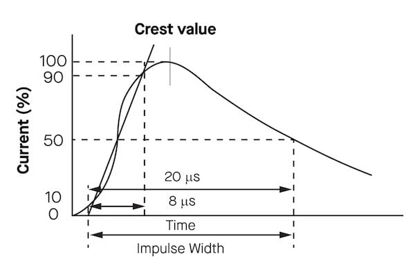
Figure 10: Typical overcurrent surge profile in solar applications
LEM has developed an HMSR evaluation board that makes it possible to prototype and test quickly the extraordinary performances of this new generation of sensors. Available as a sample on request, this new product line will enter mass production in early 2020.
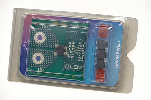
Figure 11: HMSR demo-board available for sampling
HMSR Main Technical Data
| IPN | 6..30 A |
| IPM(measuring range) | 15..75 A |
| AC Insulation Test (50 Hz, 1 min) | 4.95 kV |
| Impulse withstand voltage | 8 kV |
| dCp/dCI (mm) | 8/8 |
| Operating temperature range | -40°C…+125°C |
| Supply voltage | 5V |
| Step response time | 2uS |
| Frequency bandwidth | >270 kHz |
| Over-current detection | Yes (x2) |
About the Authors
Damien Leterrier graduated Electronics Engineering for Embedded System and Automation at ESIEE Paris. He worked as a Global Product Manager at LEM that is a focused manufacturer and global market leader in producing high-quality transducers for measuring electrical parameters.
Thomas Hargé received his Master of Science in Microelectronics at Higher School of Electronic Physics Chemistry of Lyon. He worked as a Vice President Of Product Management at LEM, which is a focused manufacturer and global market leader in producing high-quality transducers for measuring electrical parameters.
Stéphane Rollier worked as a Product Manager at LEM that is a focused manufacturer and global market leader in producing high-quality transducers for measuring electrical parameters.
This article originally appeared in the Bodo’s Power Systems magazine.