 Facebook
 Google
 GitHub
 Linkedin
20 MHz Magic: How a Slow Clock Delivers Sub-Meter Ranging Around Mars
Japan’s MMX mission relies on NEC’s LIDARX chip to achieve sub-meter ranging precision around Phobos with a 20 MHz clock, balancing space-grade reliability and dynamic range.
This week, on Tuesday, October 20, a Japan Aerospace Exploration Agency (JAXA) H3 rocket lifted off from Tanegashima Space Center. Aboard, JAXA’s Martian Moons eXploration (MMX) probe began its journey towards Phobos, one of Mars’ twin moons. The probe’s mission is unique: MMX will land on Phobos, collect surface material, and return it to Earth in 2031, making it the first sample ever returned from the Martian neighborhood.
Even more extraordinary is the technology required to do so. It requires an array of specialized equipment beyond the norm, even for a space mission.
Doing science so close to a celestial body hinges on knowing the distance to the surface at all times. Enter MMX’s LIDAR, a laser altimeter built by NEC Corporation that is based on equipment previously flown aboard JAXA’s Kaguya, Hayabusa, and Hayabusa2 missions. At its heart sits LIDARX, a pulse-detection IC that allows the instrument to resolve distances to less than a meter while its system clock runs at 20 MHz.
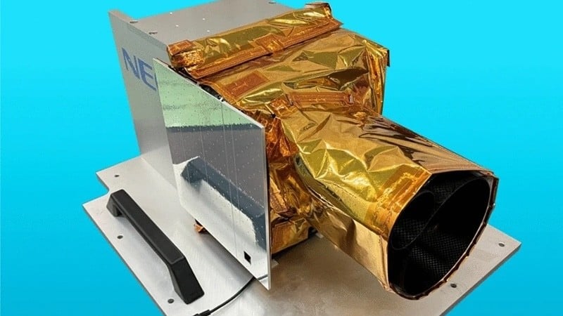
NEC’s LIDAR for the MMX mission, which will measure the distance to Phobos from as far as 100 km to as close as 100 m. Image used courtesy of Senshu et al., via Springer
Pairing sub-meter precision with what seems to be a sluggish clock sounds contradictory. However, when we analyze the physics behind laser ranging, we can appreciate the obstacles these brilliant engineers faced.
The Problem With Counting Faster
At its core, pulsed laser ranging is a stopwatch problem. We fire a pulse, time the echo, cut the round trip in half, and then multiply by the speed of light. Using this result, we see that one nanosecond of round-trip time equates to a 15cm range. This relatively simple math only gives resolution as fine as a circuit’s sense of time, so for more precision, we count faster.
Hazard avoidance on a planetary lander generally calls for 10 cm ranging resolution. Hayabusa2’s LIDAR uses a 300 MHz sample rate, giving 50 cm resolution, so a counter trying to achieve 10 cm resolution would need to reach 1.5 GHz. While that’s possible, speed in space comes with a price. High-frequency logic tends to be more prone to single-event upsets. These are bit flips that occur when an energetic particle, often a heavy ion or photon in deep space, strikes a processor or transistor.
Another problem came with dynamic range. Because MMX would need to range Phobos from 100 km to 100 m, echo strength would vary significantly—about 60 dB. Hayabusa2 used a split receiver with near- and far-range optical paths. For MMX, NEC chose a single optical system, meaning the receiver system would have to cover the entire range on its own.
The solution to both of these problems came in the form of LIDARX.
One Little Pulse of Inspiration
Each measurement starts with a passively Q-switched Nd:YAG laser, emitting a 1064 nm pulse at 22 mJ once every second. Then, after the pulse reflects off the surface, a 117.5 mm diameter mirror focuses the faint returning echo onto an avalanche photodiode (APD), which multiplies the photocurrent about 100 times.
LIDARX then takes over. First, a divider inside LIDARX scales the APD’s charge, the magnitude of which depends significantly on distance. Then, an integrator produces a leading wave by converting the charge into a voltage. The timing detector then differentiates the wave and flags the moment it crosses zero. This marks the peak of the returning light. Meanwhile, the integrator’s output height doubles as a measure of received energy.

Inside LIDARX: a divider, integrator, timing detector, and time-to-analog converter turn a faint photodiode pulse into a precise timestamp. Image used courtesy of NEC
Interpolating Between Ticks
Once the chip finds the peak of the returning light, it raises a HIT signal. The transmitter and receiver use identical peak-detection blocks, both of which operate with the same 20 MHz clock. When the transmitter’s HIT fires, a time-to-analog converter steps in to measure the time until the next rising clock edge. That edge also initiates a counter, and when the echo’s HIT arrives, the receiver’s TAC measures its own time span. This is where the counter finally stops.
The counter supplies the coarse answer at about 7.5 m per tick, or c/2f at 20 MHz. The TAC readings, which are held as analog voltages, trim the fractional ticks at both ends. This effectively pushes the resolution below a meter without the need for a high-speed clock.
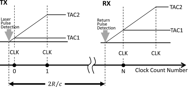
How LIDARX measures time: HIT signals from the outgoing and returning pulses start and stop a clock counter, while TACs fill in the fraction of a tick at each end. Image used courtesy of Senshu et al., via Springer
Despite all the work being done in the probe, range isn’t actually computed on board. All of the timing and energy data are sent to Earth as telemetry. Ground processing then plugs that data into the following equation:
$$R = \frac{c}{2f} \left( N + k_{\mathrm{TX}} \frac{\mathrm{TAC1}_{\mathrm{TX}}}{\mathrm{TAC2}_{\mathrm{TX}} - \mathrm{TAC1}_{\mathrm{TX}}} - k_{\mathrm{RX}} \frac{\mathrm{TAC1}_{\mathrm{RX}}}{\mathrm{TAC2}_{\mathrm{RX}} - \mathrm{TAC1}_{\mathrm{RX}}} \right) + g(a_{\mathrm{out}})$$
In this equation, N is the clock count, f stands for clock frequency, and the TAC terms are the transmit and receive interpolator readings. Electrical testing done earlier set correction factors kTX and kRX of 1.38 and 0.924, while g(a_out) corrects for residual dependence on echo strength.
The clock’s frequency is important because every tick represents 7.5 m of range. The instrument’s quartz crystal oscillator, when measured against a calibrated rubidium oscillator, runs at 19.99969 MHz at 0 °C and rises by 10.3 Hz per 1 °C. Across the 0–60 °C calibration span, that’s a 618 Hz swing. By our math, a fixed clock value at one end of the span would misjudge a 100 km range by 3 m at the other end if left uncorrected.
Automatic Gain Control for a Moving Target
Phobos is too small, and sits too close to Mars, to support an orbit like those around other planets. Because of this, MMX will circle Mars in lockstep with the moon. This comes in the form of a 7.66-hour loop that produces a quasi-satellite orbit of Phobos. Over each loop, the probe’s distance to Phobos will vary by almost a factor of two, which results in a fourfold echo energy swing. But this is more than a single gain setting can span. Complicating matters further, manual gain switching would mean sending a command to the probe every two hours—a significant demand on a team for months at a time.
So the LIDAR chooses for itself. LIDARX offers the probe five channels with 16 gains apiece. The team chose four overlapping gains per channel (0, 2, 8, and 15) that cover six orders of magnitude in received light. The internal switching logic is also deliberately lopsided—a reading below 200 mV of integrated charge triggers a step-up in sensitivity. Stepping down requires eight consecutive shots to show readings above 700 mV. To avoid unstable cycling, these thresholds are spaced so new readings fall within the window instead of triggering an immediate switch back.
When engineers completed ground calibration and channel-gain tuning prior to delivery, they chose a peak-detection threshold for each channel-gain pair. They then fitted a cubic correction for residual energy dependence. Finally, they used an optical attenuator across a range of 0 to 43 dB to simulate ascending and descending passes. Range scatter was less than 1 m whenever the echo energy stayed inside its expected operating window.
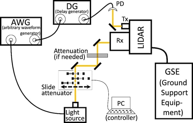
Ground calibration: a delay generator and light-signal simulator imitated a laser echo from roughly 100 km away, while a slide attenuator dimmed it from 0 to 43 dB in 1 dB steps. Image used courtesy of Senshu et al., via Springer
Slow Logic, Sharp Timing
Timing faint laser echoes isn't a problem encountered only in distant orbits; some recent LiDAR receiver ICs pair time-domain and voltage-domain converters to avoid complex time-to-digital circuitry. LIDARX goes further than this, bringing together amplification, timing detection, clock interpolation, and pulse-height management into a single IC unit.
Given its versatility, MMX may not be the last example of this kind of chip. When JAXA engineers first pitched the concept in 2011, they suggested using it for planetary landers, noting that landers and docking systems require a wide dynamic range. Lower-powered versions could even make their way to land-based rovers, both terrestrial and extraterrestrial, to map terrain and navigate independently.
With the successful launch, a collective sigh of relief and pride has surely swept through labs and assembly rooms across Japan, and deservedly so. MMX should arrive in the Martian system in August 2027, when the 20 MHz clock will face its final exam: ranging Phobos one tick at a time.