Facebook
 Google
 GitHub
 Linkedin
A Performance Comparison of GaN E-HEMTs versus SiC MOSFETs in Power Switching Applications
This article highlights GaN Systems Inc. comparison of GaN E-HEMTs and SiC MOSFET performance and characteristics in power switching applications.
Research on wide bandgap (WBG) devices has been conducted for many years. The reason that the properties of Gallium Nitride (GaN) and Silicon Carbide (SiC) excite power engineers is that they show substantial performance improvements over their silicon-based counterparts.
Characteristics of Wide Bandgap Devices
The Wide Bandgap (WBG) devices offer five key characteristics, including high dielectric strength, high-speed switching, tolerance of high operating temperature environments, high current density, and low ON-resistance. However, currently, there are few papers that compare how GaN and SiC devices perform in real power switching applications. Both GaN and SiC semiconductors have material properties superior to Si for switching power devices.
In this article, we present the results of a head-to-head comparison of GaN E-HEMTs and SiC MOSFETs used in a DC-DC synchronous buck converter application. Due to lower internal capacitances and zero reverse recovery charge, we conclusively demonstrate that GaN E-HEMTs offer significant improvements in power conversion efficiency, especially at higher frequencies.
GaN Transistor GS66508T Performance
For this study, the performance of the GaN transistor GS66508T (650 V/ 30 A, 50 mΩ) from GaN Systems Inc. was compared with the SiC MOSFET C3M0065090J (900 V/ 35 A, 65 mΩ) from CREE Inc.
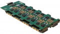
To simplify comparing the GaN E-HEMT and SiC MOSFET, the test used a common evaluation motherboard GS665MB-EVB, paired with an interchangeable daughterboard (Figures 1-4). These boards are configurable either as a buck, boost or double-pulse tester. The two daughterboards also have a very similar design. They both contain the same PCB layout, 2 oz. copper, 4 PCB layers, homogeneous thermal via and layout parasitics.
The very fast switching speeds exhibited by GaN and SiC semiconductor transistors require gate drivers, that combine very high timing accuracy with excellent common-mode transient immunity (CMTI). To accommodate these criteria, Silicon Labs’ Si8271 isolated gate driver with high CMTI was used on both daughterboards.

Figure 1: GS66508T-EVBDB

Figure 2: C3M0065090J-EVBDB

Figure 3: Bottom-side of GS66508T-EVBDB

Figure 4: GS665MB-EVB
Table 1 shows the electrical characteristics of the semiconductor devices GaN E-HEMT GS66508T and the Cree SiC MOSFET C3M0065090J. These characteristics have a major influence on the fundamental performance of the devices.

Table 1: Electrical Characteristics
A half-bridge, hard switching, double pulse test was conducted under 400 V/ 15 A on both GaN and SiC daughterboards. The turn-ON resistor Rg(on) was 10 Ω, while the turn-OFF resistor Rg(off) was 1 Ω. The results of two double pulse switching tests follow.
Figure 5 and Figure 6 show a close-up view of the turn-ON and turn-OFF periods and demonstrate the switching performance of the GaN E-HEMT GS66508T versus the SiC MOSFET C3M0065090. In the turn-ON period, dv/dt of the GaN E-HEMT reached 90 V/ns, 4X faster than the SiC MOSFET 18 V/ns. In the turn-OFF period, dv/dt of the GaN E-HEMT performed 2X faster than the SiC MOSFET.

Figure 5: Double Pulse Test Hard Switch Turn-ON

Figure 6: Double Pulse Test Hard Switch Turn-OFF
Figure 7 shows the switching loss measurements with a drain-to-source voltage of 400 V, drain current from 0 to 30 A for GS66508T and C3M0065090J. The turn-ON loss dominated the overall hard switching loss.
For GaN E-HEMT, Eon at 0 A is the Qoss, caused by the Coss at the high side switch. For the SiC MOSFET, Eon at 0 A is the sum of Qoss and the reverse recovery charge Qrr at the high side switch. Using the same test conditions, the GaN E-HEMT shows a much improved Eon/Eoff. The Eon/Eoff difference between GaN and SiC can be quantified by calculating the switching loss: (Eon+Eoff)×fsw. For example, at 400 V/ 15 A, and 100 kHz, the switching loss Psw of GaN is 5.217 W, while the Psw of SiC is 15.211 W, ∆Psw=9.994 W. However, at 200 kHz, the Psw of GaN is 10.434W, versus a SiC Psw of 30.422 W, ∆Psw=19.988 W.
The result, shown in Fig. 8, clearly shows that at higher switching frequencies, GaN provides a significant performance improvement over SiC. For instance, at 100 kHz, GaN provides 10 W savings, but in the same system at 200 kHz, 20W is saved.

Figure 7: Switching Energy of the GS66508T versus the C3M0065090J

Figure 8: 400 V/ 15 A GS66508T and C3M0065090J Switching Loss Comparison
To measure the thermal resistance Rth(JA) of both devices, a 35x35 mm heatsink was mounted on the bottom of both daughterboards. In addition, an electrical fan with an airflow of 12.0 CFM (0.340 m3/min) was attached to the heatsink.
Using the same test conditions, Rth(JA) for the C3M0065090J measured 7.724⁰C / W, versus an Rth(JA) for the GS66508T of 5⁰C / W. The thermal resistance from junction to ambient of GaN measured 1.5X better than SiC, as shown in Figures 9-11.

Figure 9: Thermal Resistance Comparison of GaN vs. SiC

Figure 10: GS66508T Thermal Resistance Setup

Figure 11: C3M0065090J Thermal Resistance Setup
A synchronous buck converter with an input voltage of 400 V and an output voltage of 200 V was tested. At a 200 kHz switching frequency, the output power varied from 100 W to 1 kW. Figure 12 compares the sync buck converter system efficiencies and the device’s hard-switching junction temperature using semiconductor devices GaN E-HEMTs versus SiC MOSFETs.
The graph shows that the efficiency and junction temperature using GaN E-HEMTs performed better than SiC MOSFETs under the same test conditions. The power loss of the devices was equal to (Tj-Tamb)/(Rth(JA)). From 0 to 1 kW, at 200 kHz GaN Ploss is only 45%-59% that of SiC. Table 2 shows the performance improvement of GaN E-HEMTs over SiC MOSFETs at an output power of 900 W. At Pout = 900 W, the Tj of the GaN E-HEMT was 59⁰C lower than the SiC MOSFET, and the power loss of GaN was 5.38 W lower than that of SiC.
The superior performance of GaN versus SiC semiconductors can be attributed to its lower Eon/Eoff. Because the conduction loss was small, the switching loss (Eon+Eoff)*fsw accounts for over 85% of the device’s total power loss. Hence, as the switching frequency increases, GaN E-HEMTs will perform better than SiC MOSFETs.

Figure 12: Synchronous Buck DC/DC System Efficiency (400 V - 200 V, 200 kHz, Tamb = 25°C)

Table 2: Power Loss and Junction Temperature Comparison at Pout = 900 W
Conclusion
This article compares the fast switching device characteristics of GaN E-HEMTs versus the best competing SiC MOSFETs. When used in synchronous buck DC/DC converter applications, the converters that use GaN E-HEMTs exhibit much higher efficiencies than ones that use SiC MOSFETs.
In this application, the results clearly demonstrate that the performance of GaN E-HEMTs exceeds the performance of the best SiC MOSFETs in terms of switching speed, parasitic capacitance, switching loss, and thermal characteristics. Furthermore, compared with their SiC semiconductor device counterparts, GaN E-HEMTs facilitate the construction of significantly more compact and efficient power converter designs.
About the Authors
Jason (Jianchun) Xu worked as a Senior Applications Engineer at GaN Systems Inc. He was responsible for doing competitive analysis on costs, power loss, efficiency, thermal and system design advantages. He also works with customers, marketing and engineering department to define product roadmaps. He earned his Bachelor's and Master's Degree in Electrical Engineering and Automation at Nanjing University of Aeronautics and Astronautics located in Jiangsu, China. He also received another Master's degree in Electrical Engineering at the University of Ottawa located in Ottawa, Canada.
Di Chen worked as a Global Application Manager at GaN Systems Inc., Ottawa Canada. He is specialized in power electronics, power supplies, as well as circuit designs. He earned his Bachelor's Degree in Electrical and Electronics Engineering at Nanjing University of Aeronautics and Astronautics, Jiangsu, China. The then acquired his Master's Degree in Electrical Engineering - Power Electronics at The University of British Columbia located in Vancouver, Canada.
This article originally appeared in the Bodo’s Power Systems magazine.