Facebook
 Google
 GitHub
 Linkedin
Modern Shunt Reactors and Static Var Compensators for Electrical Grids Can Be More Economical
This article focuses on thyristor-controlled devices for reactive power compensation that have very similar performance to TCR and SVC are more economical.
With the circuit topology presented in this article, it is possible to construct reactive power compensation devices, which are significantly more economical than comparable SVC (Static Var Compensators), though they exhibit nearly the same functional properties. The proposed circuit topology is especially advantageous in the high-voltage grids (110 kV and above) and for applications as a pure controllable shunt reactor.
Modern electrical power grids are facing many challenges due to their increasing complexity in operation and structure. Primarily their stability is often nearly exhausted [1-4]. One of the main causes of grid instability is the grid’s inability to meet the demand of reactive power [3].
The most popular means of improving the ability of a power system to ensure the required reactive power flow at the correct time is shunt compensation with controlled or uncontrolled devices [5]. Under specific conditions and for specific purposes, such as flicker reduction or damping of voltage oscillations, it is very reasonable to employ controllable reactive power compensation devices with response times of less than 20 ms, which can only be achieved by using semiconductor switches.
The first power electronic devices for reactive power compensation were static var compensators (SVC) combining thyristor-controlled reactors (TCR) and thyristor-switched capacitors (TSC) that appeared in the 1970s [6]. As the power switches with forced turn-off capability, such as IGBT or GTO, became commercially available, STATCOM (Static Synchronous Compensator) began to gain substantial market share. Although the latter provides more functionalities and advantages regarding dimensions and weight, the choice between SVC and STATCOM is influenced by a number of specific conditions and requirements. Especially at the power range above 35 Mvar, STATCOM becomes unacceptably expensive and can rarely compete with SVC.
This article focuses on thyristor-controlled devices for reactive power compensation that have very similar performance to TCR and SVC but has significant advantages in economical terms at high power applications.
Functional Overview
The main feature of the proposed circuit topology is its inductive part, which basically consists of an inductor and a transformer with a main winding and galvanically isolated control windings that are controlled by a solid state switch. The basic scheme of the inductive part is shown in Figure 1.
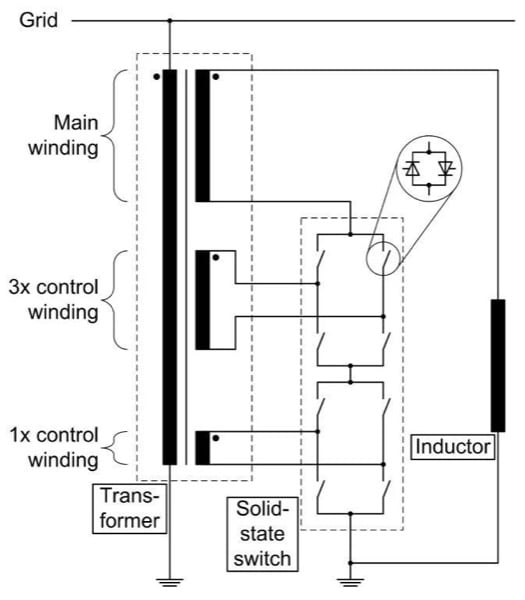
Figure 1: Circuit diagram of the inductive part
The semiconductor switch is built of one or several commutation cells. The purpose of each commutation cell is to establish a connection between the corresponding control winding and the main winding. There are three possible positions of the control winding: it can be connected in the same direction, in the reverse direction or in neutral position in relation to the main winding. For safe tap changing a safe commutation algorithm is required, which preserves the windings against short circuit. In fact, different topologies may be realized with bidirectional switches, an overview of some of them can be found in [7]. A compromise between construction complexity and achievable number of steps can be realized by, for instance, three control windings proportioned as 1x-3x-9x, resulting in 27 steps.
In this way, the effective number of turns at the high voltage side of the transformer can be varied, which controls the voltage and the current of the inductor and therefore the overall reactive power supplied by the system. Therefore, the compensated reactive power is proportional to the square of the resulting transfer ratio of the controlled transformer. The following equation defines the reactive power in the inductive range:
`Q_("Ind")=(U_("Grid")^2)/(2\pifL)*(N_("PW")/N_("SW") )^2`
whereas UGrid is the grid voltage at the connection point;
L – inductance of the inductor;
NPW – number of turns in the primary winding of the transformer;
NSW – number of turns in the secondary winding of the transformer.
The described way of operation yields some considerable advantages: firstly, the overall rated power of the semiconductor switch amounts to only half of the rated inductive power capability of the system; secondly, no harmonic filters are required, because the currents are sinus-shaped in contrast to the classical SVC, where the currents are significantly distorted due to the thyristor phase control.
Utilization as a fast controllable shunt reactor
The quadratic relationship between the transformer’s turn ratio and the compensated reactive power determines a further potential for savings in terms of investments if the control range does not approach zero.
This can be seen in Figure 2, where the control characteristic is shown. In this example, the required control range is defined from 20% to 100% of the maximum reactive power. This implies that the power rate of the semiconductor switch has to be as high as 28%, i.e. less than one third of the power rate of the system. As the semiconductor switch for the proposed circuit has two identical branches, and each of them must be rated to the whole switch power, the overall rating of the thyristors compared to a TSR (Thyristor-Switched Reactor) with only one branch will be about 56%, which is nevertheless a significant saving.
In general, the relation between the ratings of power electronic switch and maximum reactive power is defined by the following equation:
`v=(1-sqrt(Q_("min") ))/2`
where Qmin is the lowest limit of the control range or – in other words – the minimum reactive power absorbed by the device.

Figure 2: Control characteristics of windings
Fast controllable shunt reactors are becoming an important part of high-voltage power transmission lines, especially when electrical power has to be transferred to distant and abruptly changing loads. In this case, shunt reactors are used to eliminate overvoltages caused by the Ferranti effect and to increase grid stability as well as its transmission capacity [8].
Utilization of reactive power compensation in both inductive and capacitive range
The fast controllable shunt reactor described above may be combined with capacitor banks thus providing the possibility to compensate both inductive and capacitive reactive power in the electrical grid. An example of such an arrangement rated at ±100 Mvar is shown as a single-line diagram in Figure 3.
Depending on the demands of every specific application, the capacitor banks may be placed directly at the same transformer like the shunt reactor or they may be distributed over grid nodes like in the Norte de Angola energy system [9]. Two shunt reactors, each rated by 60 Mvar and 15 capacitor banks with an overall power capability amounting to 150 Mvar, were installed there in 2009. Just after several months of the installation, it has prevented a grid crash which would have happened without those devices.
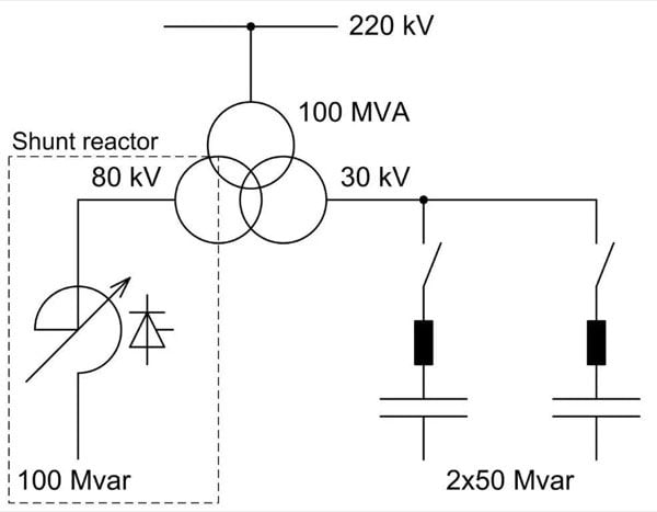
Figure 3: Single-line diagram of the full reactive power compensator
Implementation
At Maschinenfabrik Reinhausen GmbH, a laboratory model of the inductive part as well as a prototype of a solid-state switch rated at 1 kA and 15 kV (1x-3x-9x winding segmentation) were designed and successfully tested.
Figures 4 and 5 show voltage and current diagrams while one of the control windings was switched from neutral to the same direction regarding to the main winding and then vice versa. In the first case, the voltage and current of the inductor were both increased thus increasing the reactive power consumed by the system. In the second case, the system was returned into the original state.
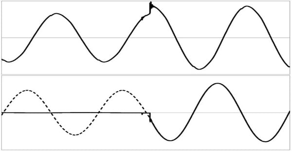
Figure 4: Switching a control winding from neutral to the same direction regarding to the main winding. Top: voltage across the inductor; Bottom: current in the inductor or in the main winding (dashed line) and in the control winding (solid line)
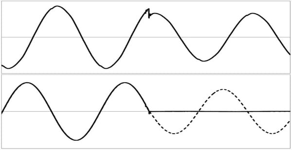
Figure 5: Switching a control winding from the same to neutral direction regarding to the main winding. Top: voltage across the inductor; Bottom: current in the inductor or in the main winding (dashed line) and in the control winding (solid line)
A prototype of the power electronic switch is shown in Figure 6.
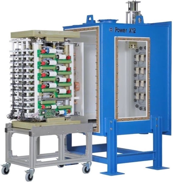
Figure 6: Power electronic switch for transformer control rated at 15MW, 1x-3x-9x winding segmentation topology
Conclusions
Thyristor-based means of supporting electrical power grids are remaining advantageous for high-voltage lines and networks, especially if high reactive power capacity is required.
The new technical approach of reactive power compensation presented in this paper allows design of economical systems with nearly the same functional characteristics as broadly known SVC. Due to reduced costs, the range of reasonable applications of reactive power compensation devices may be enlarged. Cost-effective fast controllable shunt reactors allow operation of long power transmission lines with rapidly changing load conditions.
In this paper, the functional characteristics of the new circuit topology for reactive power compensation were explained. Compared to SVC, it has many advantages that allow cost-effective compensation of reactive power in electrical power grids.
About the Author
Andrey Gavrilov works as the Development Engineer for Hardware and Software at Maschinenfabrik Reinhausen, Regensburg, Germany, a company active in power engineering and consists of Maschinenfabrik Reinhausen GmbH. Their core business is the regulation of power transformers which is done above all with the aid of tap changers, which adapt the transmission ratio of the primary to secondary winding to changing load ratios and, together with additional, innovative products and services, ensure interruption-free power supply.
References
- N. Mithulananthan, S. C. Srivastava: Investigation of a voltage collapse incident in Sri Lankan power system network, Singapore: International Conference on Energy Management and Power Delivery ’98, 1998
- IEEE/PES Power System Stability Subcommittee: Voltage stability assessment: concepts, practices and tools, Special Publication, Final document, 2002
- C. A. Canizares, F. L. Alvarado: Point of collapse and continuation methods for large AC/DC systems, IEEE Transactions on Power Systems 8(1), 1993
- A. C. Zambroni de Souza: Discussion on some voltage collapse indices, Electrical Power System Research 53(1), 2000
- A. J. Schwab: Elektroenergiesysteme. Erzeugung, Transport, Übertragung und Verteilung elektrischer Energie. 3., neu bearbeitete und erweiterte Auflage, Berlin: Springer-Verlag, 2012
- R. Mohan Mathur, Rajiv K. Varma: Thyristor-Based FACTS Controllers for Electrical Transmission Systems, New York: John Wiley & Sons, 2002
- A. Gomez Exposito, D. Monroy Berjillos: Solid-State Tap Changers: New Configurations and Applications, IEEE Transactions on Power Delivery, Volume: 22, Issue: 4, 2007
- A. Dimitrovski, Z. Li, B. Ozpineci: Applications of Saturable-core Reactors (SCR) in Power Systems, T&D Conference and Exposition, 2014 IEEE PES
- V. S. Chuprikov, D. S. Mologin: Implementation of a pilot SCRT in the electrical power system Norte de Angola, Yekaterinburg: Publishing house “Vsja electronica”, Energoexpert, Nr 1 (18), 2010
- S. P. Engel, R. W. De Doncker: Control of thyristor-based commutation cells, Energy Conversion Congress and Exposition (ECCE), 2012
This article originally appeared in the Bodo’s Power Systems magazine.